
Pixel circuit

a display device and pixel technology, applied in the field of display devices, can solve the problems of increasing the quality of display devices, long time of light-emitting elements reaching the target brightness, and consumers may easily experience the phenomenon of motion blur, so as to reduce the phenomenon of display flicker and the response tim

Active Publication Date: 2020-07-30
AU OPTRONICS CORP
View PDF0 Cites 0 Cited by
  • Summary
  • Abstract
  • Description
  • Claims
  • Application Information

AI Technical Summary

Benefits of technology

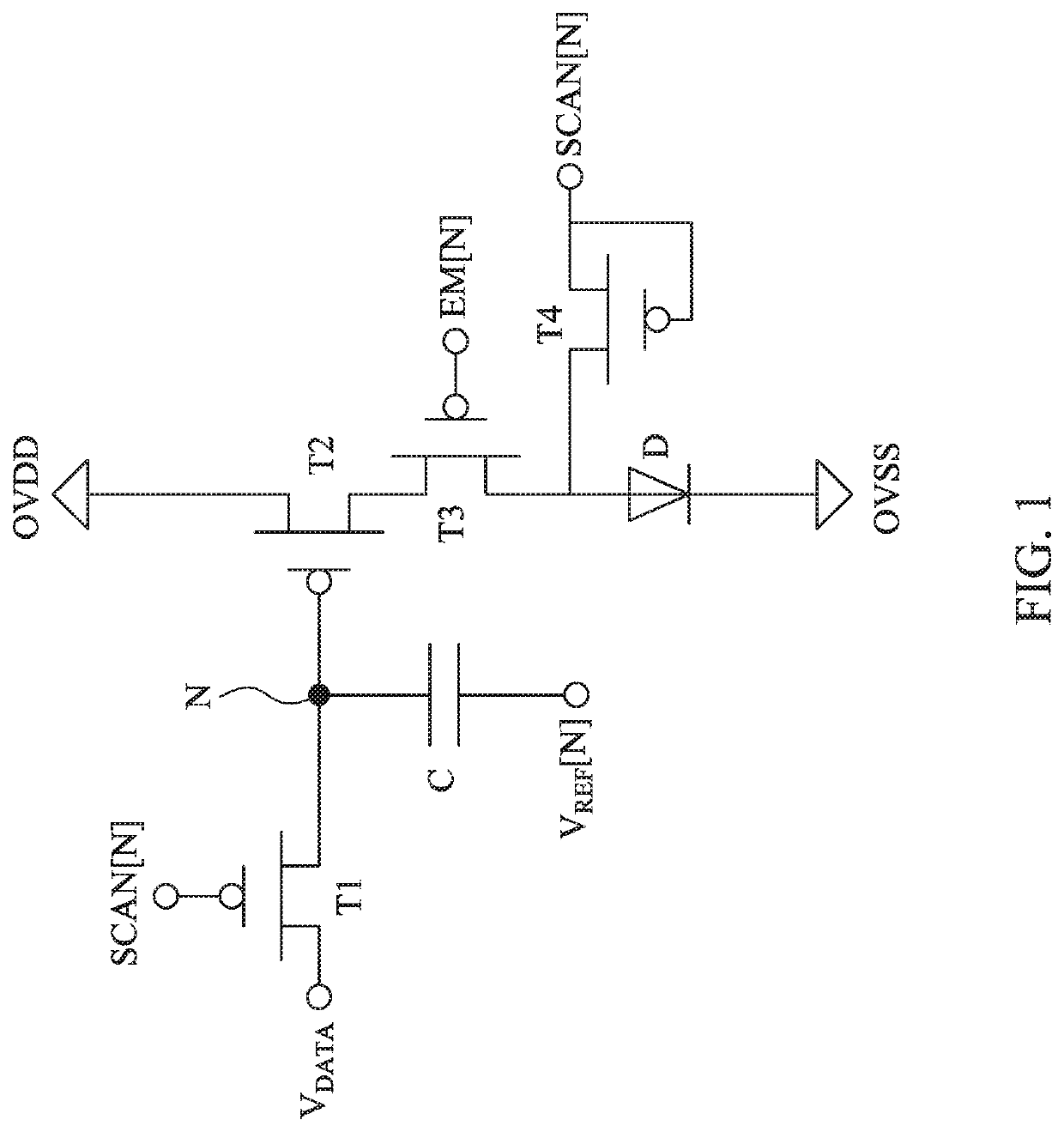
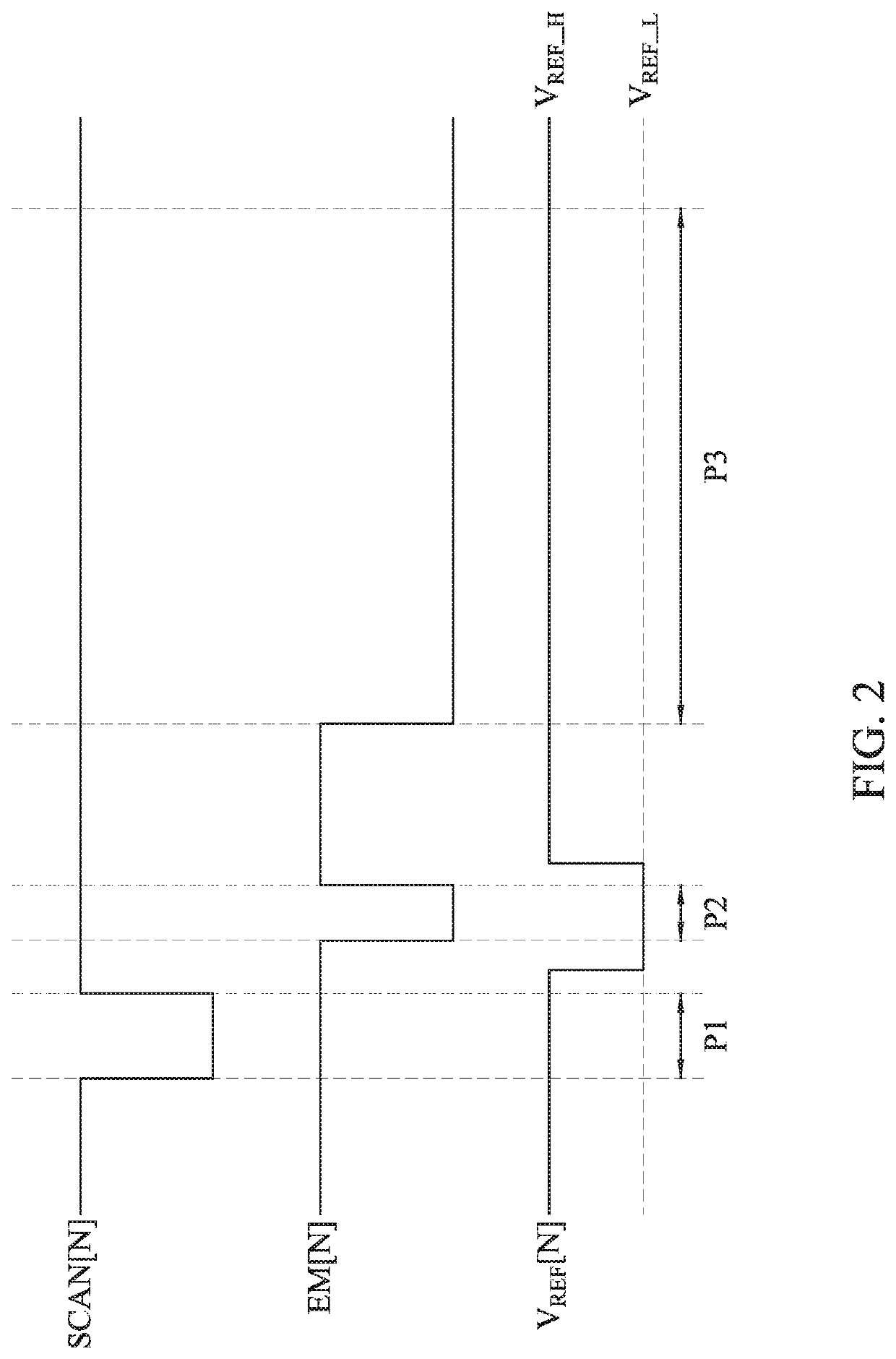
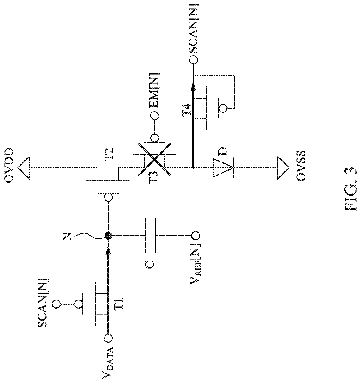
[0007]Therefore, according to the technical content of the present disclosure, the embodiment of the present disclosure provides a pixel circuit. The different current is provided by the adjustment of the reference signal under the same data voltage. Once the pixel circuit provides a large current by the above technical features, the response

Problems solved by technology

With the advance of technology, consumers are increasingly demanding the quality of display devices.
However, in this driving mode, the response time of the light-emitting element reaching the target brightness is long, and consumers may easily experience the phenomenon of motion blur.
If the illumination ratio has a time frame which is too low,

Method used


Image

  • Pixel circuit
  • Pixel circuit
  • Pixel circuit

Examples


Embodiment Construction

[0020]The following is a detailed description of the embodiments in order to provide a better understanding of the scope of the present invention, but the embodiments are not intended to limit the scope of the disclosure, and the description of the structural operation is not limited. The order in which they are performed, any structure that is recombined by the elements, produces equal means of function, and is covered by the disclosure. In addition, according to industry standards and practices, the drawings are only for the purpose of auxiliary explanation, and are not drawn according to the original size. In fact, the dimensions of various features can be arbitrarily increased or decreased for explanation. In the following description, the same elements will be denoted by the same reference numerals for convenience of understanding.

[0021]The terms used in this specification and claims, unless otherwise stated, generally have their ordinary meanings in the art, within the context...


PUM


Abstract

A pixel circuit is disclosed herein, which includes a first switch, a capacitor, a driving transistor, and a light-emitting diode (LED). The first switch outputs voltage data in response to a scan signal. A first terminal of the capacitor and the first switch are coupled to a node. A second terminal of the capacitor receives a reference signal. The driving transistor is coupled to the node, and configured to output current according to a voltage stored in the node. The LED is coupled to the driving transistor, and emits light according to the current. The reference voltage is different during different operation periods. The driving transistor outputs a first current according to the voltage data and the voltage difference, and outputs a second current according to the voltage data during different operation periods, such that the LED emits a first light and a second light during different operation periods.

Description

RELATED APPLICATIONS[0001]This application claims priority to Taiwan Application Serial Number 108103363, filed Jan. 29, 2019, which is herein incorporated by reference in its entirety.BACKGROUNDField of Invention[0002]The present of the disclosure relates to a display device. More particularly, the present disclosure relates to a pixel circuit of a display device.Description of Related Art[0003]With the advance of technology, consumers are increasingly demanding the quality of display devices. Under this requirement, when a display device wants to display a target brightness during a frame time, in general, to provide a normal driving current of a light-emitting element (such as a light-emitting diode) and a long emission ratio in order to cause the human eye to generate a brightness integral to sense a perceived target brightness. However, in this driving mode, the response time of the light-emitting element reaching the target brightness is long, and consumers may easily experien...

Claims


Application Information

Patent Timeline
IPC IPC(8): G09G3/32
CPCG09G2300/0819G09G2310/0267G09G3/32G09G2300/0842G09G2320/02G09G3/3233G09G2300/0861G09G2320/045G09G2310/08G09G2320/0247G09G2320/0257G09G2320/0233
Inventor CHEN, YI-CHIUNGCHENG, MAO-HSUN
Owner AU OPTRONICS CORP
Features
  • Generate Ideas
  • Intellectual Property
  • Life Sciences
  • Materials
  • Tech Scout
  • Unparalleled Data Quality
  • Higher Quality Content
  • 60% Fewer Hallucinations
Learn More