Imaging lens
a technology of imaging and lens, applied in the field of imaging lenses, can solve the problems of inability to obtain excellent optical performance, difficult to correct aberrations at a peripheral area, etc., and achieve the effects of low f-number, correcting aberrations properly, and high resolution
- Summary
- Abstract
- Description
- Claims
- Application Information
AI Technical Summary
Benefits of technology
Problems solved by technology
Method used
Image

Examples
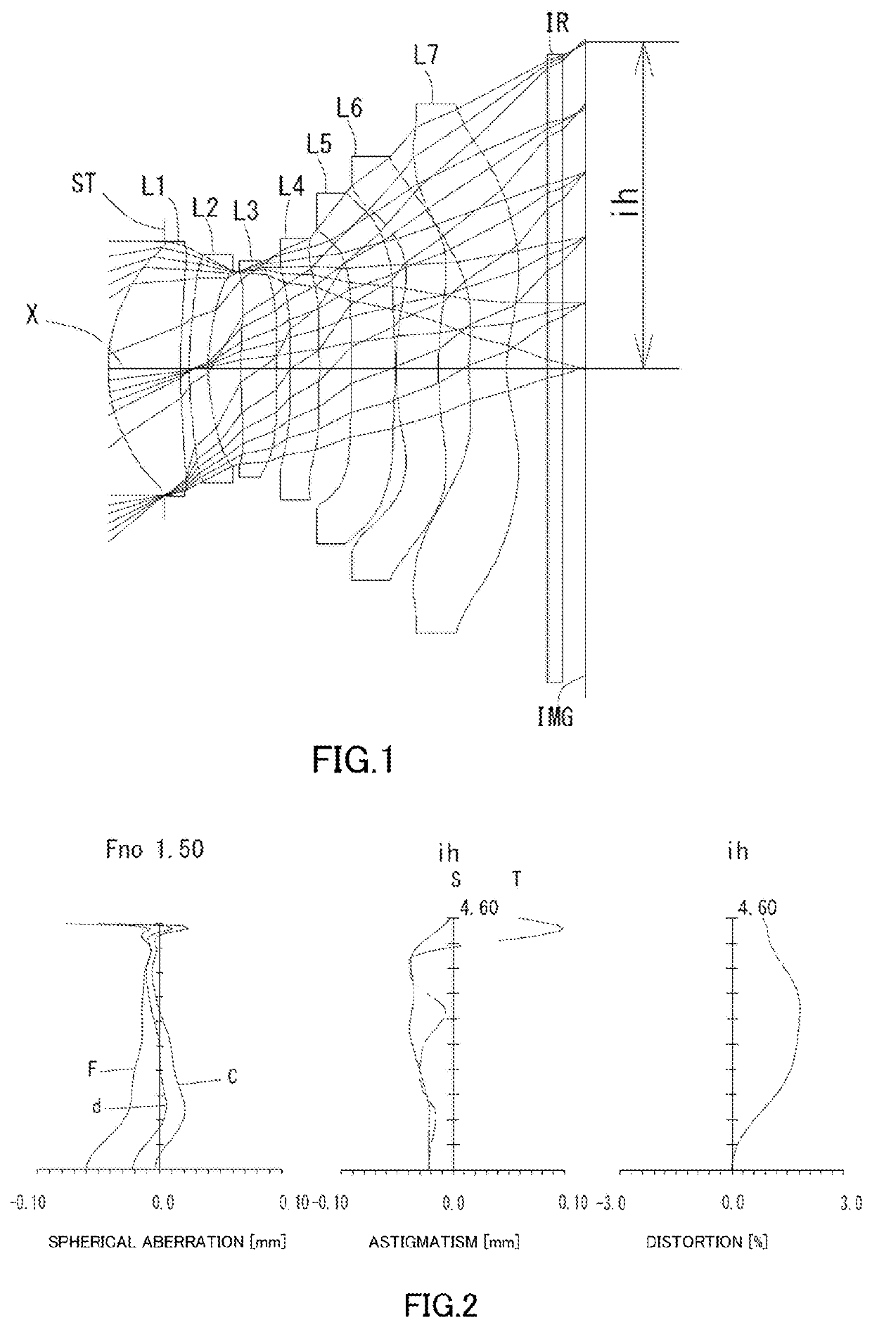
example 1
[0181]The basic lens data is shown below in Table 1.
TABLE 1Example1Unit mmf = 5.60Fno = 1.50ω(°) = 38.9ih = 4.60TTL = 6.64Surface DatairdNdνd(Object)InfinityInfinity1(Stop)Infinity−0.79812*2.25311.01821.54455.88 (νd1)3*7.85040.12364*4.46680.27001.67119.48 (νd2)5*3.00430.45696*9.23440.49751.53555.66 (νd3)7*84.48760.19508*Infinity0.41381.54455.8 (νd4)9*Infinity0.450110* −14.31250.51701.67119.48 (νd5)11* −5.80880.015012* 6.12820.58911.54455.86 (νd6)13* 5.11130.437914* 5.53060.52761.53555.66 (νd7)15* 2.03640.575618 Infinity0.21001.51784.2019 Infinity0.3167Image PlaneConstituent Lens DataLensStart SurfaceFocal LengthComposite Focal LengthEntrance pupil diameter125.456f3419.341EPd3.73524−14.7523619.34148Infinity51014.150612−71.113714−6.352Aspheric Surface DataSecond SurfaceThird SurfaceFourth SurfaceFifth SurfaceSixth SurfaceSeventh SurfaceEighth Surfacek 0.000000E+000.000000E+00 0.000000E+000.000000E+00 0.000000E+00−6.443085E+01−1.000000E+00A4−4.367540E−03−3.974717E−02 −8.997080E−02−5.19...
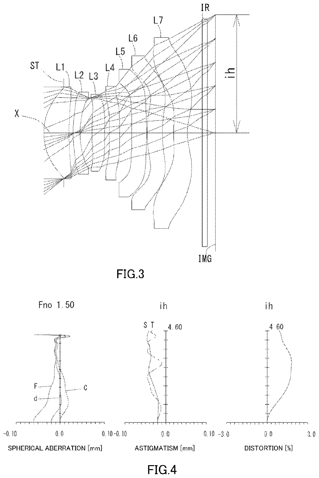
example 2
[0184]The basic lens data is shown below in Table 2.
TABLE 2Example2Unit mmf = 5.60Fno = 1.50ω(°) = 38.8ih = 4.60TTL = 6.63Surface DatairdNdνd(Object)InfinityInfinity1(Stop)Infinity−0.76982*2.27600.98261.54455.86 (νd1)3*7.52500.16024*4.08130.27001.67119.48 (νd2)5*2.93690.47136*10.53560.49721.53555.68 (νd3)7*−1427.75 00.18318*Infinity0.40001.67119.48 (νd4)9*Infinity0.474110* −13.41270.58061.67119.48 (νd5)11* −5.89340.015012* 6.06030.50101.54455.86 (νd6)13* 5.18770.434514* 5.69730.53901.53555.66 (νd7)15* 2.02790.575618 Infinity0.21001.51754.2019 Infinity0.3116Image PlaneConstituent Lens DataLensStart SurfaceFocal LengthComposite Focal LengthEntrance pupil diameter125.624f3419.558EPd3.73424−17.2343619.55848Infinity51015.187612−87.423714−6.205Aspheric Surface DataSecond SurfaceThird SurfaceFourth SurfaceFifth SurfaceSixth SurfaceSeventh SurfaceEighth Surfacek 0.000000E+000.000000E+00 0.000000E+000.000000E+00 0.000000E+00−6.443085E+01 0.000000E+00A4−1.479570E−03−3.716529E−02 −8.068441E−02...
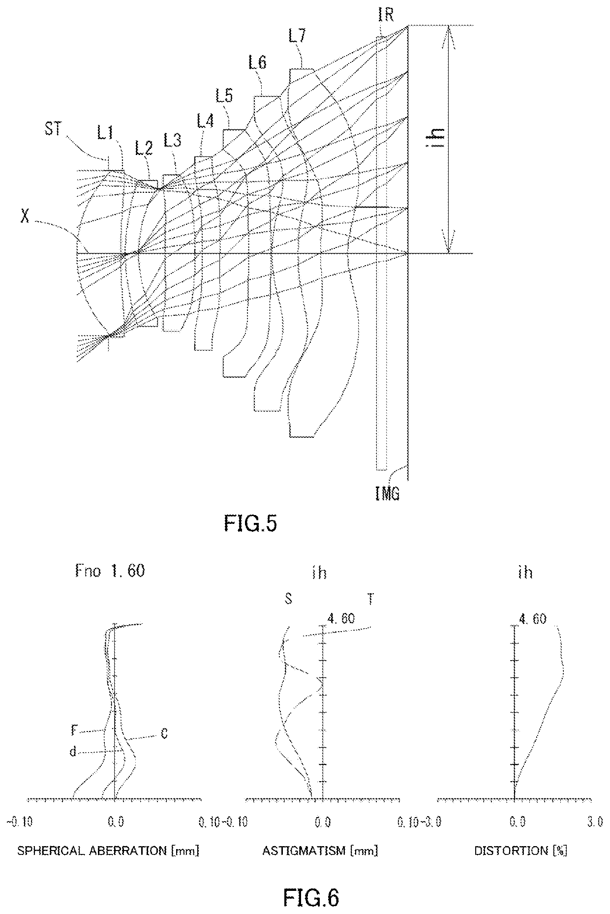
example 3
[0187]The basic lens data is shown below in Table 3.
TABLE 3Example3Unit mmf = 5.57Fno = 1.60ω(°) = 39.0ih = 4.60TTL = 6.63Surface DatairdNdνd(Object)InfinityInfinity1(Stop)Infinity−0.64722*2.27470.89001.54455.88 (νd1)3*6.92320.09324*3.02520.27001.67119.48 (νd2)5*2.34620.54186*27.14970.59691.53555.66 (νd3)7*−20.14360.14838*Infinity0.36881.67119.48 (νd4)9*Infinity0.580010* −10.43910.45001.67119.48 (νd5)11* −13.13460.015012* 3.09150.53121.54455.86 (νd6)13* 5.62150.452514* 3.59350.55011.53555.66 (νd7)15* 1.68200.575618 Infinity0.21001.517 4.2019 Infinity0.4268Image PlaneConstituent Lens DataLensStart SurfaceFocal LengthComposite Focal LengthEntrance pupil diameter125.831f3421.718EPd3.48024−18.5263621.71848Infinity510− 1.21361211.750714−6.419Aspheric Surface DataSecond SurfaceThird SurfaceFourth SurfaceFifth SurfaceSixth SurfaceSeventh SurfaceEighth Surfacek 0.000000E+000.000000E+000.000000E+00 0.000000E+000.000000E+00 0.000000E+00−1.000000E+00A4−7.054604E−03−6.298515E−02 −1.043938E−01 −...
PUM
 Abstract
Description
Claims
Application Information
PatSnap Eureka turns technology decisions into work you can execute. Powered by our Innovation Knowledge Graph, it runs expert workflows across engineering, life sciences, materials and intellectual property. Get your review-ready output in minutes.


