Pneumatic Tire and Method for Manufacturing the Same

a pneumatic tire and pneumatic technology, applied in the field of pneumatic tires, can solve the problems of lowering productivity, requiring much time and effort for vulcanized pneumatic tires, etc., and achieve the effect of accurate application

Pending Publication Date: 2020-09-10
YOKOHAMA RUBBER CO LTD
View PDF7 Cites 0 Cited by
  • Summary
  • Abstract
  • Description
  • Claims
  • Application Information

AI Technical Summary

Benefits of technology

[0012]In the present technology, the indicator is preferably expressed as a marking for identification made of a letter, a number, a symbol or a graphic. As a result, in a c

Problems solved by technology

Since the tire inner surface does not include any marks to indicate the appropriate position at which to apply a sound absorbing member or a sealant layer, applying

Method used


Image

  • Pneumatic Tire and Method for Manufacturing the Same
  • Pneumatic Tire and Method for Manufacturing the Same
  • Pneumatic Tire and Method for Manufacturing the Same

Examples


Embodiment Construction

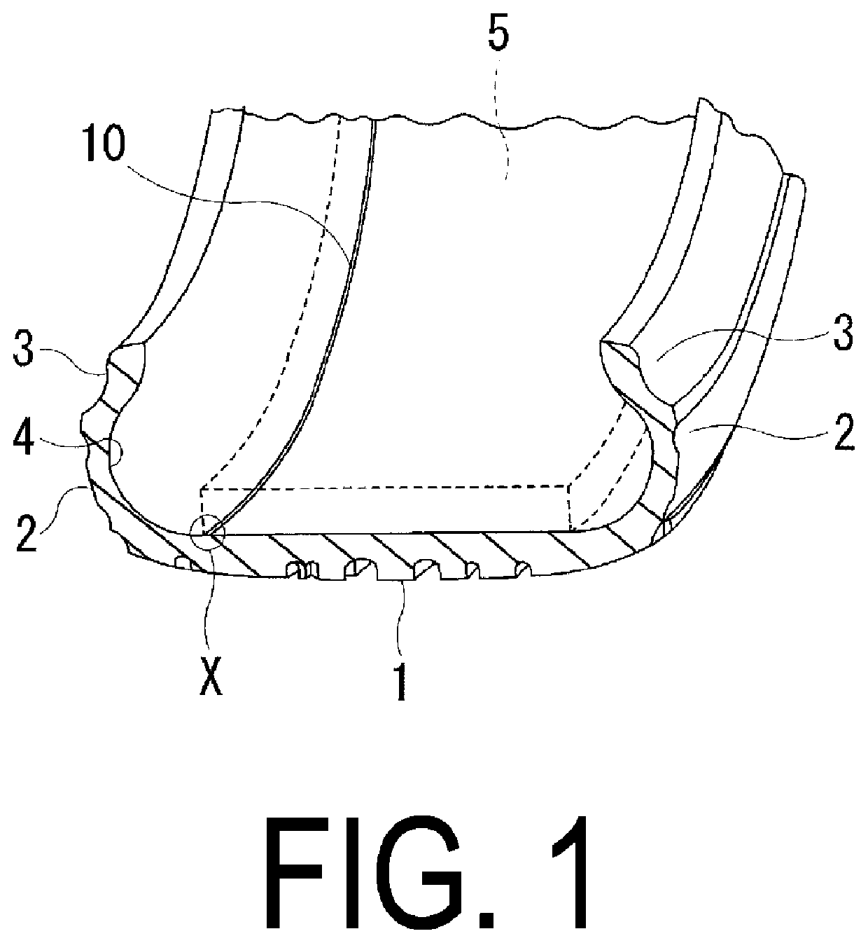
[0019]Configurations of embodiments of the present technology will be described in detail below with reference to the accompanying drawings. FIG. 1 illustrates a pneumatic tire according to an embodiment of the present technology. In FIG. 1, the pneumatic tire according to the present embodiment includes an annular tread portion 1 extending in the tire circumferential direction, a pair of sidewall portions 2 disposed on either side of the tread portion 1, and a pair of bead portions 3 disposed inward of the sidewall portions 2 in the tire radial direction. An inner liner layer (not shown) is disposed on a tire inner surface 4.

[0020]In the pneumatic tire described above, a sound absorbing member 5 is applied to a region of the tire inner surface 4 corresponding to the tread portion 1 along the tire circumferential direction. The sound absorbing member 5 can be bonded to the tire inner surface 4 using an adhesive or double-sided adhesive tape. The sound absorbing member 5 is made of a...


PUM

PropertyMeasurementUnit
Angleaaaaaaaaaa
Angleaaaaaaaaaa
Depthaaaaaaaaaa

Abstract

Provided is a pneumatic tire including an indicator made of a protrusion portion or a recess portion extending in a tire circumferential direction is formed on a tire inner surface. A sound absorbing member or a sealant layer is applied to the tire inner surface along the indicator.

Description

TECHNICAL FIELD[0001]The present technology relates to a pneumatic tire and a method for manufacturing the same and particularly relates to a pneumatic tire and a method for manufacturing the same that can provide improved productivity when applying a sound absorbing member or a sealant layer to a tire inner surface.BACKGROUND ART[0002]In general, the outer surface of a bladder, which is used when vulcanizing a green tire, is formed with a plurality of exhaust grooves (recesses) extending in the radial direction. These grooves are provided to evacuate air between the tire inner surface and the bladder to the outside (see, for example, Japan Unexamined Patent Publication No. 2014-84007). As a result, a plurality of protrusions that correspond to the recesses in the outer surface of the bladder are formed on the inner surface of a vulcanized pneumatic tire.[0003]Since the tire inner surface does not include any marks to indicate the appropriate position at which to apply a sound absor...

Claims


Application Information

Patent Timeline
IPC IPC(8): B29D30/06B60C19/00
CPCB60C19/002B29D30/0681B29C33/02B60C19/122B29D2030/0695B29D30/0685B60C19/12B29D2030/0655B29D30/0654
Inventor HOSHIBA, TAKASHINARUSE, MASAHIRO
Owner YOKOHAMA RUBBER CO LTD
Why Eureka
Try Eureka