Distance measuring sensor and distance measuring method
- Summary
- Abstract
- Description
- Claims
- Application Information
AI Technical Summary
Benefits of technology
Problems solved by technology
Method used
Image
Examples
first embodiment
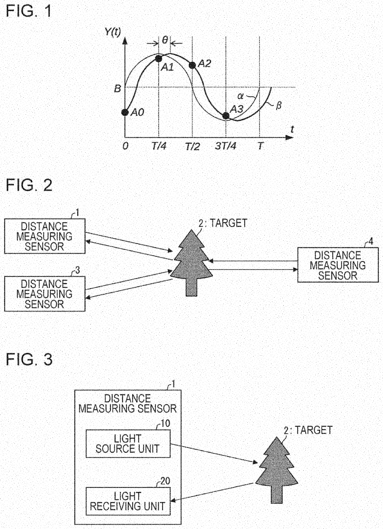
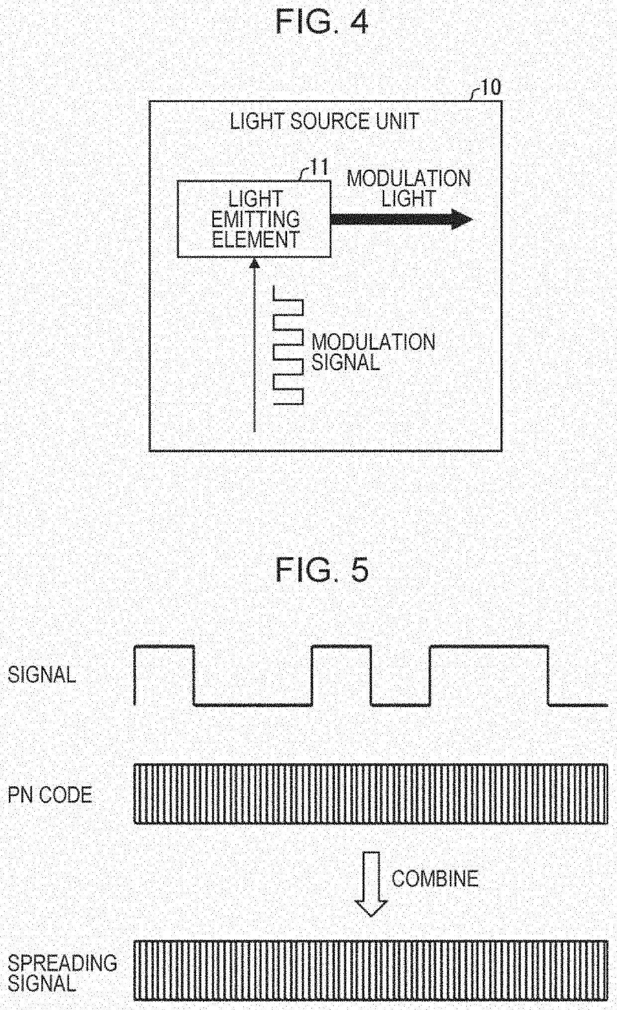
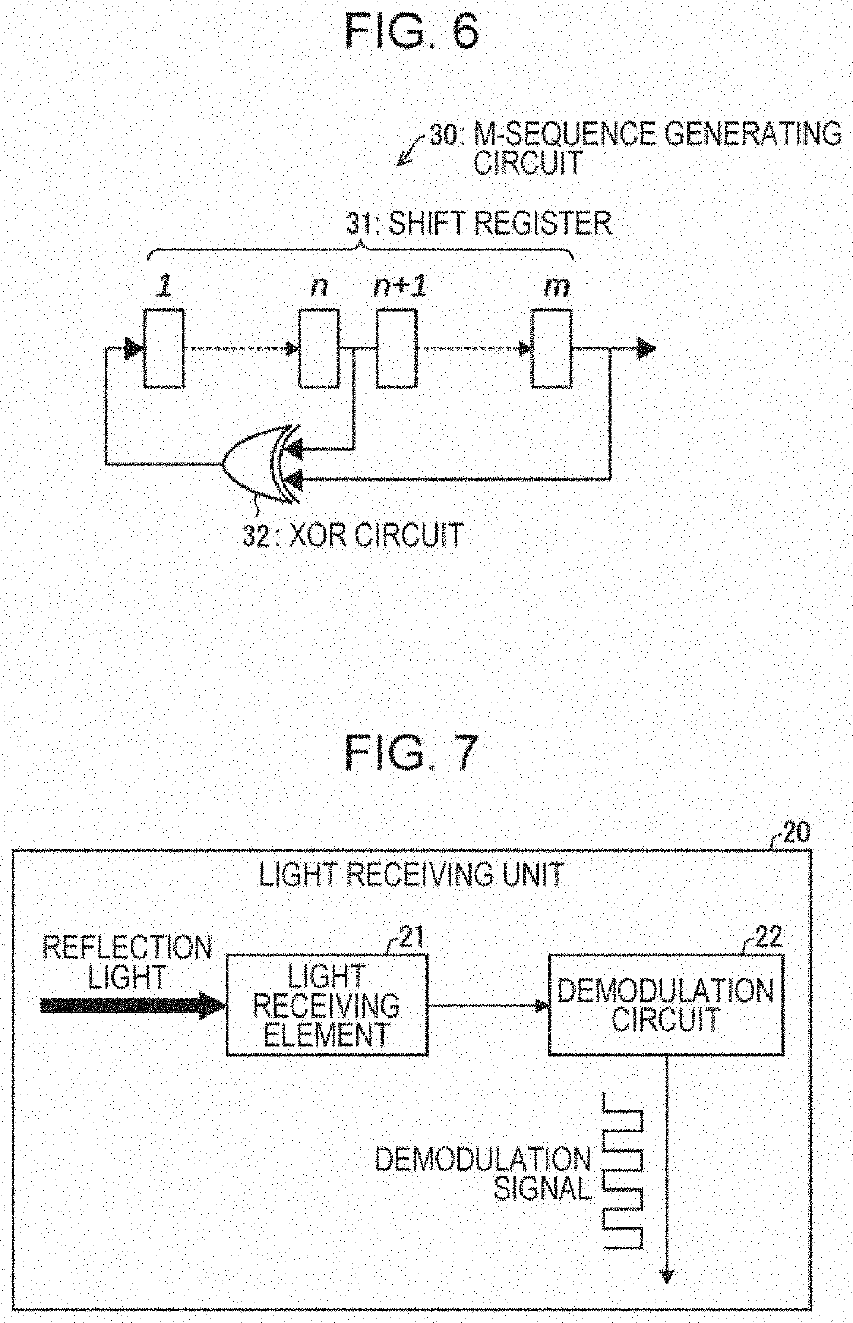
[0038]A distance measuring sensor 1 according to a first embodiment of the disclosure will be described below using FIGS. 3 to 8.
[0039][Distance Measuring Sensor 1]
[0040]FIG. 3 is a diagram showing the configuration of the distance measuring sensor 1 according to the first embodiment of the disclosure. As shown in FIG. 3, the distance measuring sensor 1 is a TOF-system distance measuring sensor that comprises a light source unit 10 and a light receiving unit 20.
[0041]In the distance measuring sensor 1, the light source unit 10 radiates irradiation light to a target 2, and the light receiving unit 20 receives reflection light reflected by the target 2. The distance measuring sensor 1 measures a time from when the light source unit 10 radiates the irradiation light to the target 2 until the light receiving unit 20 receives the reflection light reflected by the target 2. That is, the distance measuring sensor 1 measures a round-trip time (a time of flight) of light. Based on the measur...
second embodiment
[0057]Next, a distance measuring sensor 1a according to a second embodiment of the disclosure will be described using FIGS. 9 to 11. For convenience of description, members having the same functions as the members described in the first embodiment are denoted by the same reference numerals, and descriptions thereof are omitted.
[0058][Distance Measuring Sensor 1a]
[0059]FIG. 9 is a diagram showing the configuration of the distance measuring sensor 1a according to the second embodiment of the disclosure. As shown in FIG. 9, the distance measuring sensor 1a comprises a light source unit 10a and a light receiving unit 20a, instead of the light source unit 10 and the light receiving unit 20 in the distance measuring sensor 1 according to the first embodiment. Except for this point, the distance measuring sensor 1a has a configuration that is analogous to that of the distance measuring sensor 1 according to the first embodiment.
[0060][Light Source Unit 10a]
[0061]The configuration of the li...
third embodiment
[0068]Next, a distance measuring sensor 1b according to a third embodiment of the disclosure will be described using FIGS. 12 to 14. For convenience of description, members having the same functions as the members described in the above embodiments are denoted by the same reference numerals, and descriptions thereof are omitted.
[0069][Distance Measuring Sensor 1b]
[0070]FIG. 12 is a diagram showing the configuration of the distance measuring sensor 1b according to the third embodiment of the disclosure. As shown in FIG. 12, the distance measuring sensor 1b comprises a light source unit 10b and a light receiving unit 20b, instead of the light source unit 10a and the light receiving unit 20a in the distance measuring sensor 1a according to the second embodiment. Except for this point, the distance measuring sensor 1b has a configuration that is analogous to that of the distance measuring sensor 1a according to the second embodiment.
[0071][Light Source Unit 10b]
[0072]The configuration o...
PUM
 Abstract
Description
Claims
Application Information
 - R&D
- Intellectual Property
- Life Sciences
- Materials
- Tech Scout
- Unparalleled Data Quality
- Higher Quality Content
- 60% Fewer Hallucinations
Browse by: Latest US Patents, China's latest patents, Technical Efficacy Thesaurus, Application Domain, Technology Topic, Popular Technical Reports.
© 2025 PatSnap. All rights reserved.Legal|Privacy policy|Modern Slavery Act Transparency Statement|Sitemap|About US| Contact US: help@patsnap.com


