
Screen

a technology of polarizers and screens, applied in the field of screens, can solve the problems of complex structure and manufacturing process of polarizers, higher cost, and large screens, and achieve the effect of reducing manufacturing costs and easy manufacturing

Active Publication Date: 2014-04-29
SEIKO EPSON CORP
View PDF12 Cites 0 Cited by
  • Summary
  • Abstract
  • Description
  • Claims
  • Application Information

AI Technical Summary

Benefits of technology

The invention provides a screen that can reduce costs by simplifying its structure and manufacturing process and improve contrast by reducing the influence of environment light. The screen configuration allows for higher light reflectance for one polarization state and reduces the reflectance of environment light. Additionally, using metal nanorods in the polarization layer can simplify manufacturing and reduce costs. Overall, the invention improves the performance of the screen for better image quality and reduced cost.

Problems solved by technology

The structures and manufacturing processes of these polarizers are complicated and the larger the screen, the higher the cost.

Method used


Image

  • Screen
  • Screen
  • Screen

Examples


first embodiment

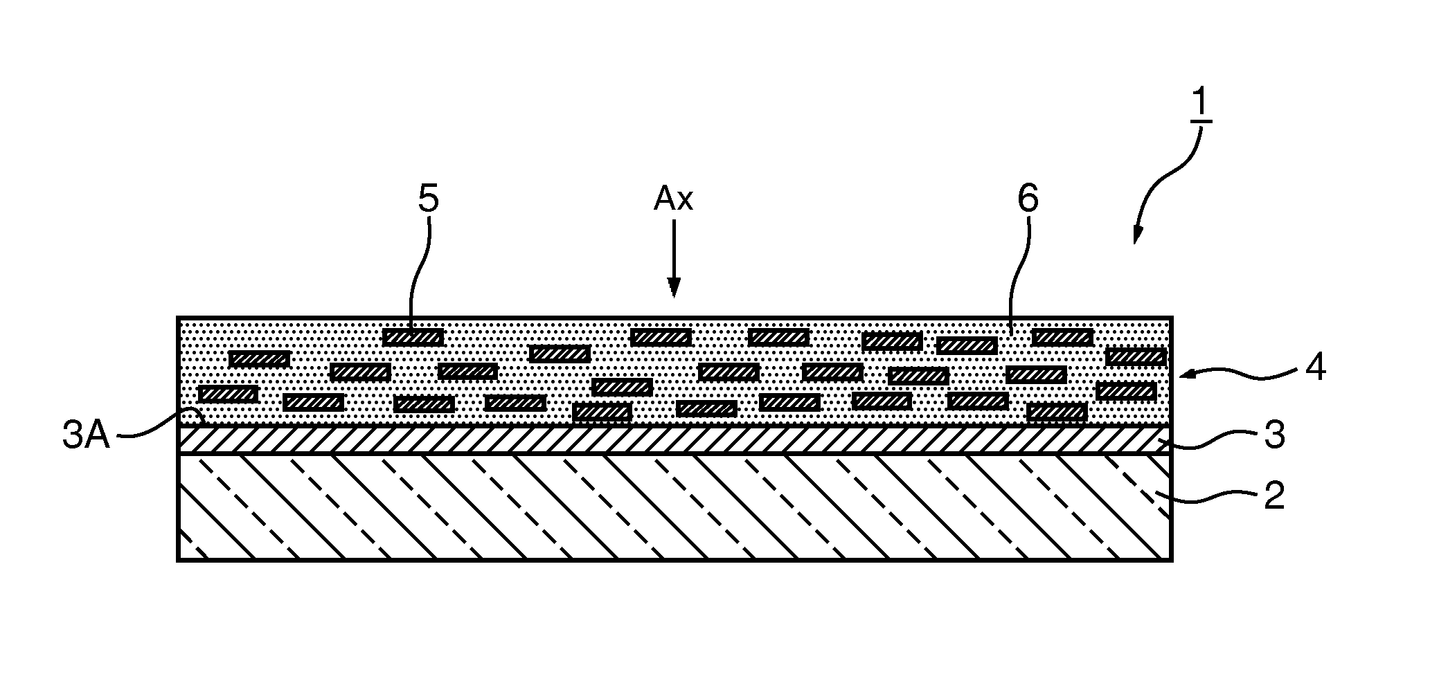
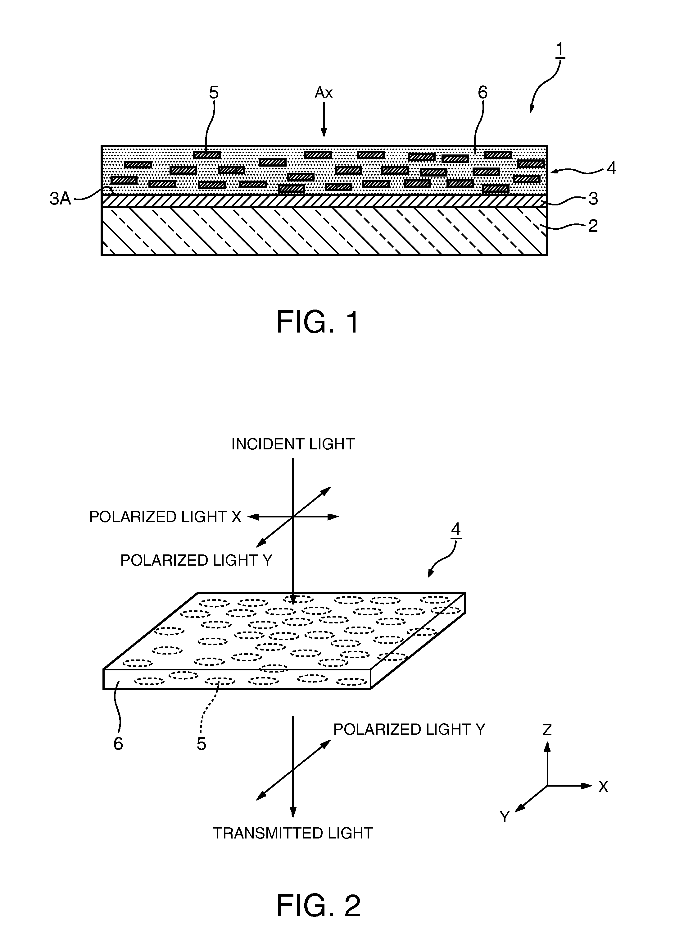
[0027]FIG. 1 is a sectional view showing a schematic configuration of a reflective screen as the first embodiment of the invention.

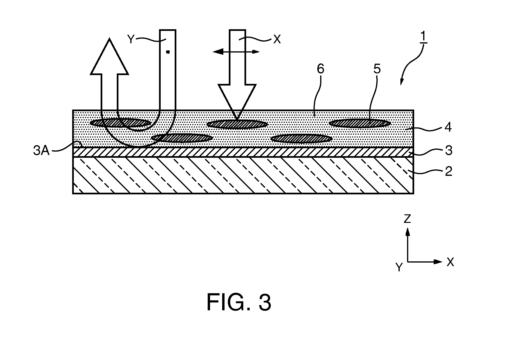
[0028]A reflective screen (hereinafter, simply referred to as “screen”) 1 of the embodiment has a configuration in which a reflection film (reflecting member) 3 and a polarization layer 4 are stacked in this order on a flexible substrate (substrate) 2, and has a polarization selectivity of reflecting or absorbing light having a predetermined wavelength.

[0029]The specific material of the flexible substrate 2 is not particularly limited and any known resin may be used. Not particularly limited to the flexible substrate, but a glass substrate, a quartz substrate, a sapphire substrate, or the like may be used. In addition to the light-transmissive materials, opaque materials may be used.

[0030]In the polarization layer 4, plural nanorods (acicular particles) 5 are dispersed in a transparent layer 6 with their major axes aligned nearly in the same direction. H...

second embodiment

[0052]FIG. 5 is a sectional view showing a configuration of a reflective screen of the second embodiment.

[0053]The basic configuration of the reflective screen of the embodiment as below is nearly the same as that of the first embodiment, but different in the configuration of the polarization layer. Accordingly, in the following explanation, the polarization layer will be explained in detail, and the explanation of the common parts will be omitted. Further, in the drawings used for explanation, the same signs will be assigned to the component elements in common with the above described embodiment.

[0054]As shown in FIG. 5, a reflective screen (hereinafter, simply referred to as “screen”) 20 of the embodiment includes a polarization layer 14 in which plural reflective nanorods 15 with their major axes oriented nearly in the same direction and a light absorbing layer (light absorbing member) 8 provided at the rear surface (flexible substrate 2) side in the transparent layer 6.

[0055]In ...


PUM


Abstract

A screen includes a polarization layer having plural acicular particles provided with their major axes oriented nearly in the same direction on a substrate, and has polarization selectivity of reflecting light in one polarization direction and absorbing light in the other polarization direction of two polarization directions orthogonal to each other on a plane perpendicular to incident light.

Description

[0001]The entire disclosure of Japanese Patent Application No. 2011-147187, filed Jul. 1, 2011 is expressly incorporated by reference herein.BACKGROUND[0002]1. Technical Field[0003]The present invention relates to a screen.[0004]2. Related Art[0005]Patent Document 1 (JP-T-2002-540445) has disclosed a configuration of a reflective projection screen combined with a projector. Here, when a projection screen having a reflective polarization element is used with a projector that generates polarized light and the polarization state of the light from the projector is a polarization state reflected by the reflective polarization element, most of the light is reflected by the screen.[0006]In Patent Document 1, as a specific configuration example of the reflective polarization element, a multilayer reflective polarizer, a continuous / discontinuous phase reflective polarizer, a cholesteric reflective polarizer (combined with a quarter-wave plate), and a wire grid polarizer have been cited. The ...

Claims


Application Information

Patent Timeline
Patent Type & Authority Patents(United States)
IPC IPC(8): G03B21/56G03B21/60G02B5/08G02B5/30G03B21/604
CPCG02B5/3008G03B21/604G03B21/60
Inventor KENMOCHI, NOBUHIKO
Owner SEIKO EPSON CORP
Learn More