

Exposure apparatus, exposure method, and device manufacturing method
a technology of exposure apparatus and manufacturing method, applied in the field of exposure apparatus, can solve the problems of increasing the manufacturing cost of microdevices and increasing the cost of the devi
- Summary
- Abstract
- Description
- Claims
- Application Information
AI Technical Summary
Benefits of technology
Problems solved by technology
Method used
Image

Examples
first embodiment
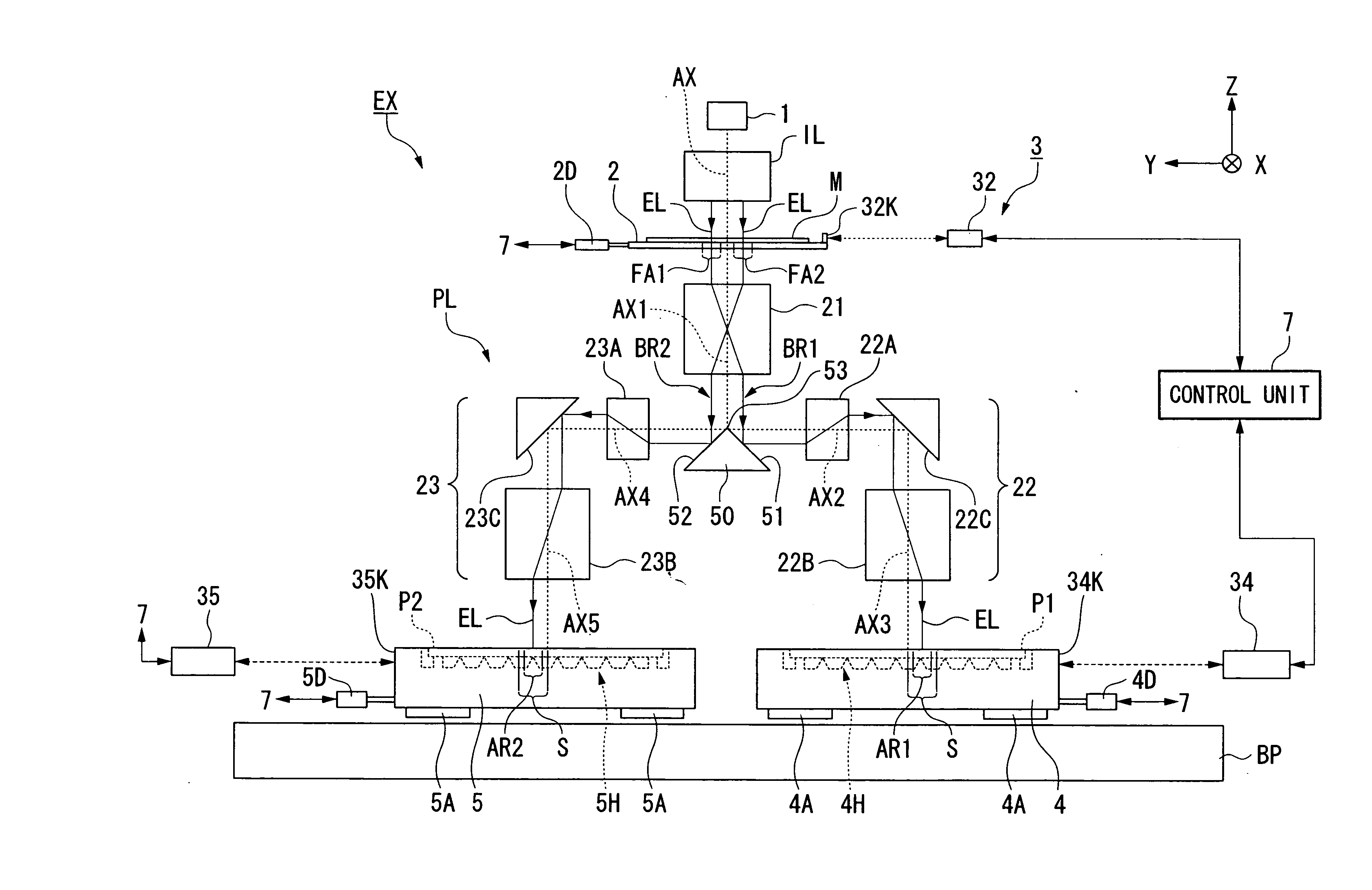
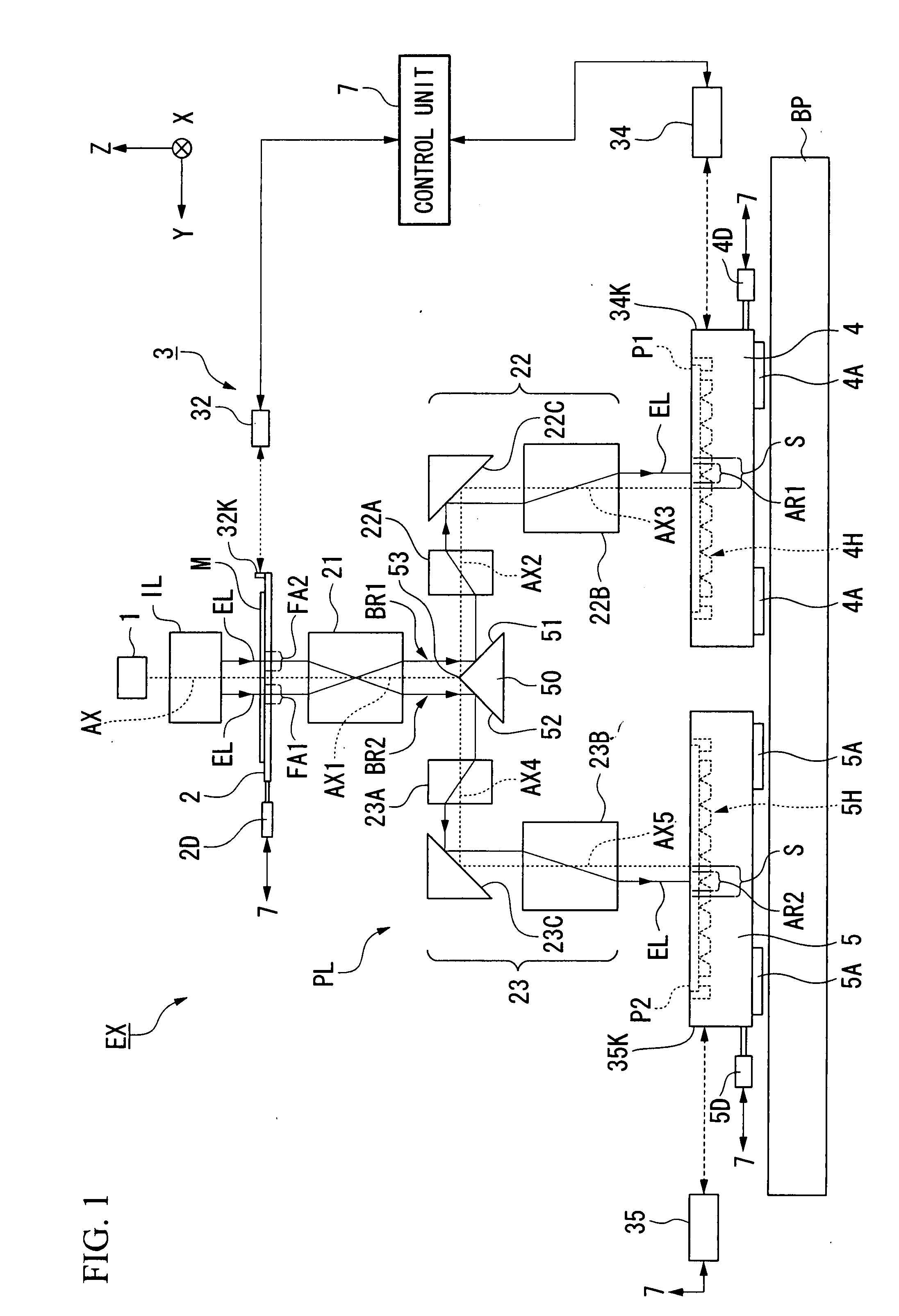
[0025] A first embodiment will be described. FIG. 1 is a schematic block diagram showing an exposure apparatus EX according to the first embodiment. In FIG. 1, the exposure apparatus EX includes; a mask stage 2 capable of holding and moving a mask M having a pattern PA, a first substrate stage 4 capable of holding and moving a first substrate P1, a second substrate stage 5 capable of holding and moving a second substrate P2 different from the first substrate P1, a measurement system 3 capable of measuring position information of the respective stages, a first illumination system IL that illuminates the pattern PA of the mask M with a first exposure light EL1, a projection optical system PL that projects an image of the pattern PA illuminated by the exposure light EL onto the respective first substrate P1 and the second substrate P2, and a control unit 7 that controls the operation of the overall exposure apparatus EX. The first substrate stage 4 and the second substrate stage 5 are ...
second embodiment
[0062] Next is a description of a second embodiment with reference to FIG. 4 and FIG. 5. The characteristic part of this embodiment is the point that a substrate stage 4′ has a main stage 40, a first substage 41, and a second substage 42. The main stage 40 is capable of holding a first substrate P1 and a second substrate P2 and moving in substantially the same scanning direction, on the light emitting side (image surface side) of the projection optical system PL. The first substage 41 is capable of moving the first substrate P1 with respect to the main stage 40. The second substage 42 is capable of moving the second substrate P2 with respect to the main stage 40. In the following description, components the same as or equivalent to those in the abovementioned embodiment are denoted by the same reference symbols, and their description is simplified or omitted.
[0063]FIG. 4 is a schematic diagram showing an exposure apparatus EX according to the present embodiment, and FIG. 5 is a sec...
third embodiment
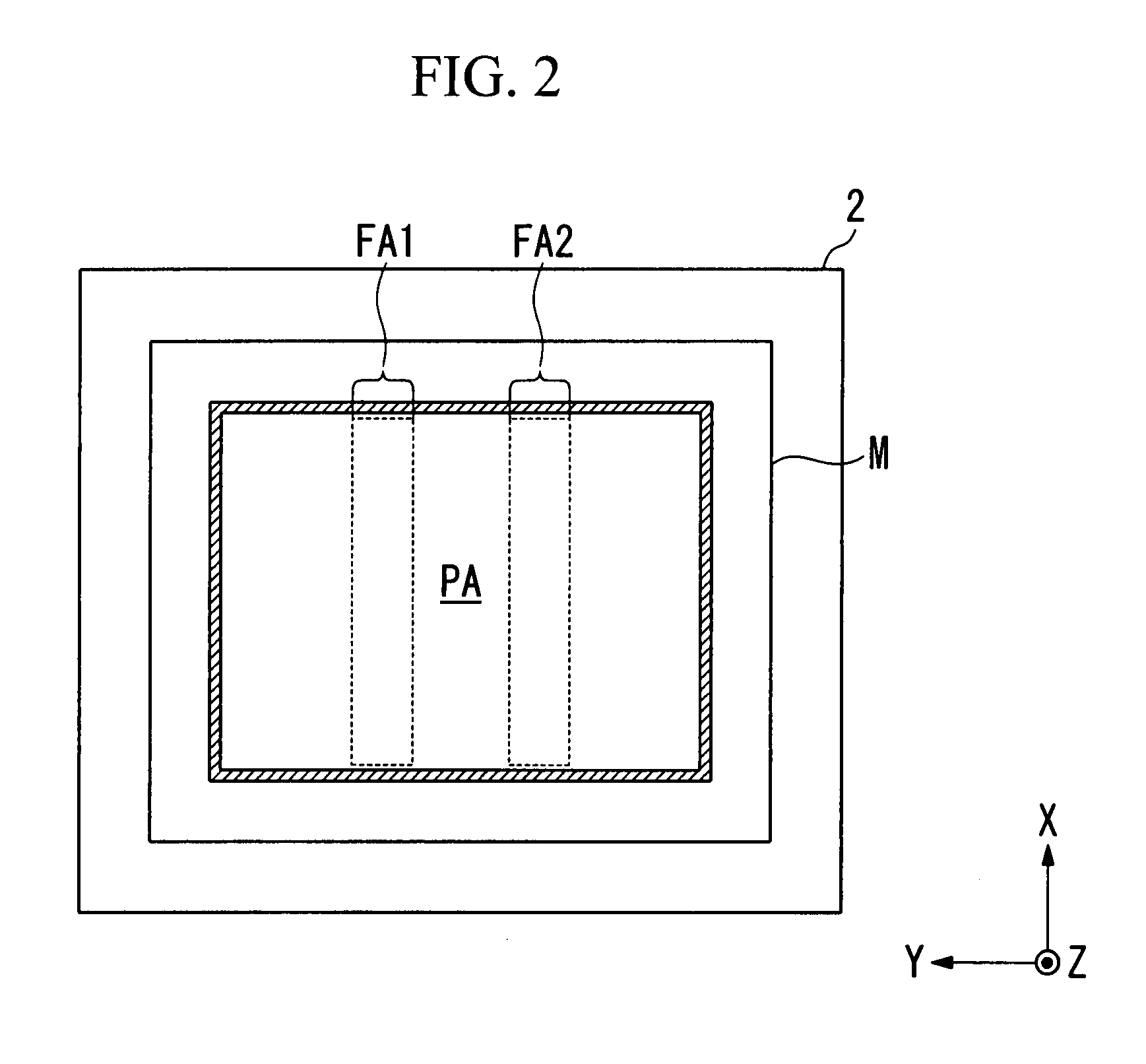
[0076] Next is a description of a present embodiment with reference to FIG. 6A and FIG. 6B. In the above embodiments, the illumination system IL divides the exposure light EL emitted from the light source device 1 into two exposure lights EL, and irradiates the divided exposure lights EL respectively onto the first object field area FA1 and the second object field area FA2. A characteristic point of this embodiment is that the exposure light EL is not divided, but the exposure light EL is irradiated onto both the first object field area FA1 and the second object field area FA2.
[0077]FIG. 6A is a plan view showing the mask M held on the mask stage 2 according to the present embodiment, and FIG. 6B is a diagram showing a state in which the exposure light EL having passed through the mask M is irradiated onto the optical member 50.
[0078] As shown in FIG. 6A, in the present embodiment, the illumination system IL does not divide the exposure light EL, but irradiates the exposure light ...
PUM
 Abstract
Description
Claims
Application Information