Method for manufacturing a bearing ring member

a manufacturing method and bearing ring technology, applied in the direction of engine components, mechanical equipment, transportation and packaging, etc., can solve the problems of limited freedom of design for maintaining the durability of the rolling bearing unit b>1/b>, the inability to achieve both a higher degree of reduction in manufacturing cost, and the inability to maintain the rolling bearing unit durability. , to achieve the effect of improving the freedom of design, simplifying the work, and maintaining the durability of the rolling bearing uni

Active Publication Date: 2013-04-23
NSK LTD
View PDF5 Cites 3 Cited by
  • Summary
  • Abstract
  • Description
  • Claims
  • Application Information

AI Technical Summary

Benefits of technology

[0029]With the manufacturing method for a bearing ring member of the present invention as described above, the metal material of the highly pure middle cylindrical portion of the raw material is exposed in at least the portion of the outer-ring races ways, which are located at two locations around the inner peripheral surface of the ring member and separated in the axial direction, where the load of the rolling bodies that acts. Therefore, it is possible to improve the freedom of design for maintaining the rolling fatigue life of the outer-ring raceways, and for maintaining the durability of a rolling bearing unit for wheel support that includes the bearing ring member that comprises these outer-ring raceways. In addition, the highly pure metal material is exposed in the portion of the outer-ring raceways where the load of the rolling bodies acts even when the dimension in the axial direction (thickness) of the partitioning section is made small, so by simplifying the work of removing the partitioning section and by improving the yield rate of the material, it is possible to keep the manufacturing cost from rising.
[0030]Also, by applying suitable construction from among the forms described above as needed, it is possible to effectively expose the metal material of the middle cylindrical portion to the surface portion of each of the outer-ring raceways in accordance to the position in the axial direction of the outward facing flange and the position of each of the outer-ring raceways.
[0032]Furthermore, by punching out and removing the partitioning section after the later stage intermediate member has been made, it is possible to remove excess metal material and to obtain a lightweight rolling bearing unit for wheel support. Instead of making the thickness of other parts, such as the cylindrical portion where the outer-ring raceways are formed thin, it is possible to apply construction that makes it possible to maintain strength by the partitioning section; where in this case, the process for removing the partitioning section is not necessary.
[0032]Furthermore, by punching out and removing the partitioning section after the later stage intermediate member has been made, it is possible to remove excess metal material and to obtain a lightweight rolling bearing unit for wheel support. Instead of making the thickness of other parts, such as the cylindrical portion where the outer-ring raceways are formed thin, it is possible to apply construction that makes it possible to maintain strength by the partitioning section; where in this case, the process for removing the partitioning section is not necessary.

Problems solved by technology

Moreover, when metal material having low purity that exists near the center or outer peripheral surface is exposed in the portion of the raceway surface provided on the surface of the bearing ring member, it becomes difficult to maintain the rolling fatigue life of that portion.
Therefore, in the prior known manufacturing method for a bearing ring member, the freedom of design for maintaining the durability of the rolling bearing unit 1 for wheel support is limited.
However, as shown in (C) of FIG. 12, it is not possible to achieve both a higher degree of reduction in manufacturing cost and improvement of durability by just improving the formation location of the partitioning section 19.
However, from the state shown in (C) of FIG. 12, by further compressing the partitioning section 19, the metal material 12 of the circular column shaped portion near the center moves to the portion that will become the both of the outer-ring raceways 5, and it becomes difficult to maintain the rolling fatigue life of both of these outer-ring raceways 5.

Method used


Image

  • Method for manufacturing a bearing ring member
  • Method for manufacturing a bearing ring member
  • Method for manufacturing a bearing ring member

Examples


first embodiment

[First Embodiment]

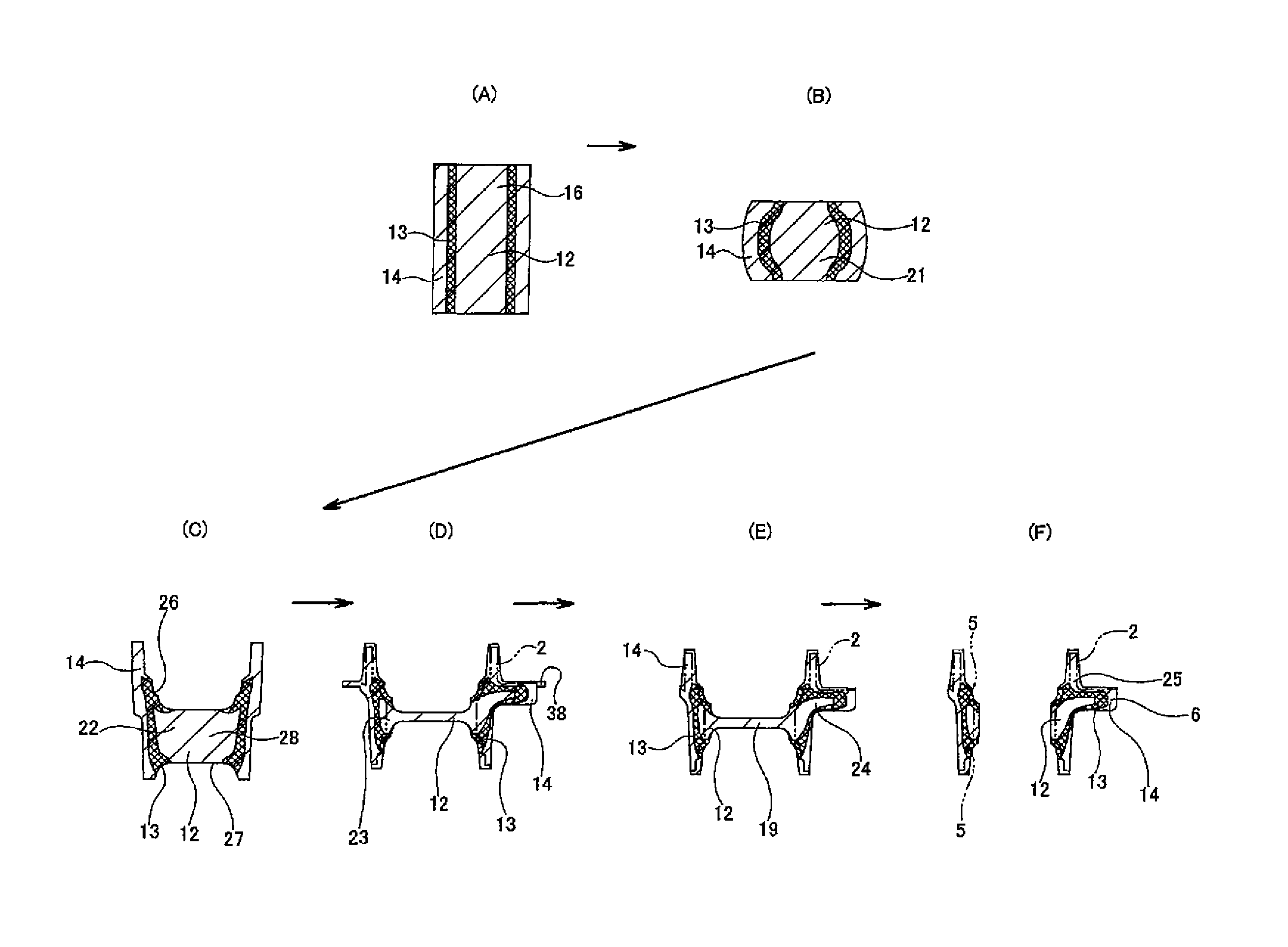
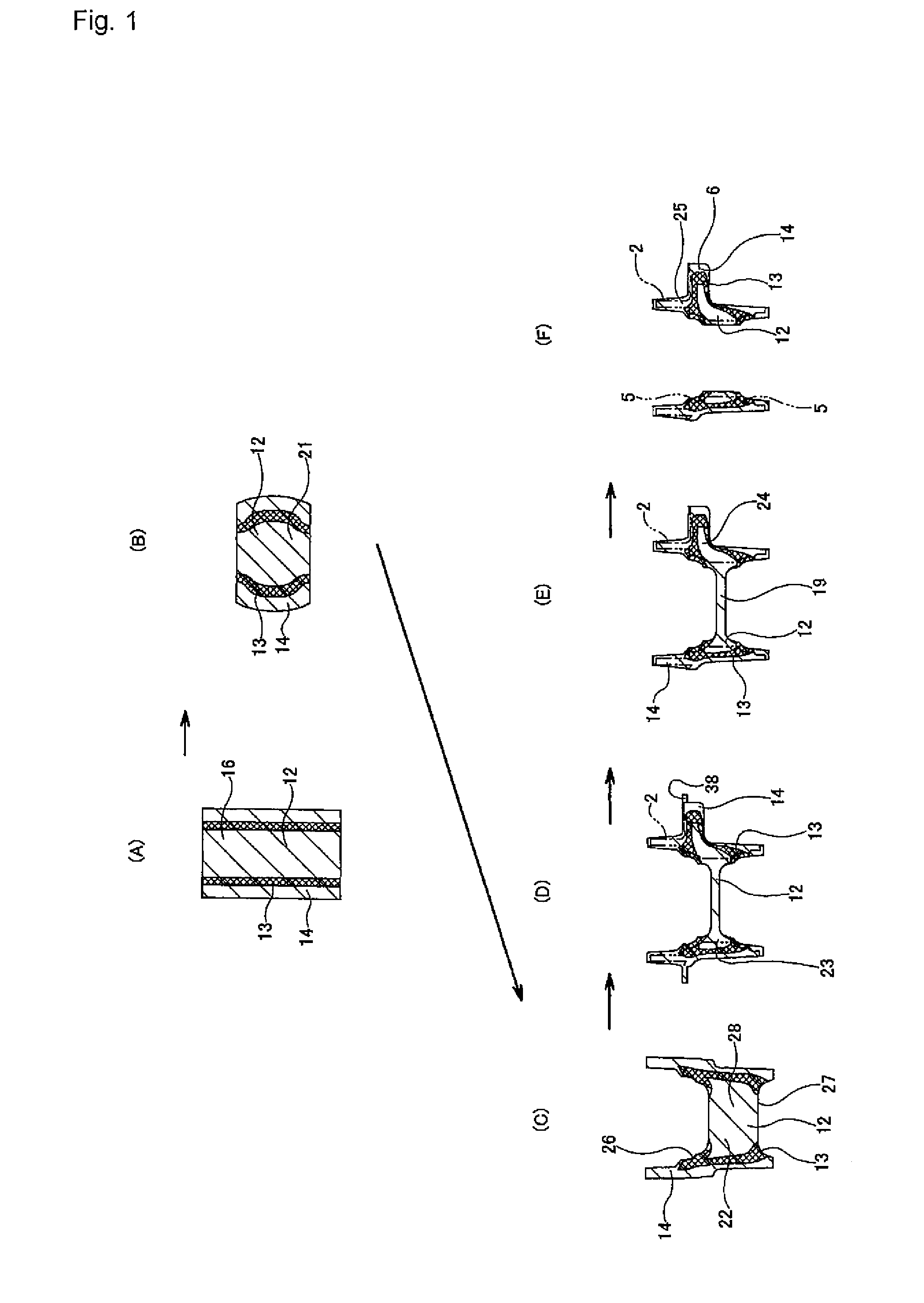
[0045]FIGS. 1 to 4 shows a first embodiment of the present invention. The manufacturing method of this first embodiment sequentially performs plastic working or punching on a metal circular column shaped raw material 16 such as a steel alloy like medium carbon steel, bearing steel or carburized steel that can be quench hardened after plastic working as shown in (A) of FIG. 1. Also, going through a preliminary stage intermediate member 21 shown in (B), and second preliminary stage intermediate member 22 shown in (C), a post-preliminary stage intermediate member 23 shown in (D), and a later stage intermediate member 24 shown in (E), obtains the final stage intermediate member 25 shown in (F). Furthermore, the manufacturing method performs the necessary cutting and grinding on this final stage intermediate member 25 to obtain an outer ring 2 of an inner-ring rotating type rolling bearing unit 1 for wheel support as shown in FIG. 7 and described above. The volume of th...

second embodiment

[Second Embodiment]

[0060]FIG. 5 shows a second embodiment of the present invention. In this embodiment, the forward-backward extrusion process that was performed in the first embodiment described above is omitted. In other words, the second upsetting process shown in FIG. 2 and described above is performed directly on the preliminary stage intermediate member 21 that is shown in (B) of FIG. 5 to obtain the post-preliminary stage intermediate member 23a shown in (C) of FIG. 5, and then the burrs 38 are removed to obtain the later stage intermediate member 24a shown in (D) of FIG. 5 and in FIG. 6. This kind of embodiment can be applied for a case in which plastic working is performed all at once such as when the outer ring to be manufactured is small, or when the size of the press apparatus for performing the press processing is large. In this embodiment, the distribution of metal material 12 of the circular column shaped portion near the center, the metal material 13 of the middle cy...


PUM

PropertyMeasurementUnit
outer diameteraaaaaaaaaa
outer diametersaaaaaaaaaa
shapeaaaaaaaaaa

Abstract

The present invention provides a manufacturing method of a bearing ring member such as an outer ring comprising an installation portion on the outer peripheral surface and a double row of outer-ring raceways on the inner peripheral surface, in which a raw material is processed to obtain a final stage intermediate member through a first upsetting process, a forward-backward extrusion process, a second upsetting process, a burr removing process, and a punching process, wherein a movable die which leaves a stationary die in the final step is used in the second upsetting process, and the excess metal material is moved toward outside in the radial direction to a portion which become the installation section and a burr formation section, exposing a high pure metal material at least in a portion where the load of rolling bodies acts so as to ensure the rolling fatigue life of the both of outer-ring raceways.

Description

FIELD OF THE INVENTION[0001]The present invention relates to improvement of a method for manufacturing a bearing ring member of a rolling bearing unit for wheel support that is used for supporting wheels of an automobile or a rotating member for braking such as a brake disc with respect to a suspension apparatus. The bearing ring that is the object of the manufacturing method of the present invention comprises: a double row of back-to-back-arrangement outer-ring raceways at two locations in the axial direction around the inner peripheral surface thereof; and an outward facing flange around the outer peripheral surface thereof. This kind of bearing ring member corresponds to an outer ring that is connected and fastened to the suspension apparatus in the case when the aforementioned rolling bearing unit for wheel support is an inner-ring rotating type, and corresponds to a hub that supports and is fastened to a wheel and rotates with that wheel in the case when the above rolling beari...

Claims


Application Information

Patent Timeline
Patent Type & Authority Patents(United States)
IPC IPC(8): B21D22/00B21K1/40
CPCB21K1/04F16C19/185F16C19/186F16C33/64Y10T29/49533F16C2326/02Y10T29/49679Y10T29/49636
Inventor KOBAYASHI, KAZUTOKOYAMA, HIROSHIYASUDA, YUU
Owner NSK LTD
Why Eureka
Try Eureka