
Exposure apparatus, exposure method and device fabricating method

a technology of exposure apparatus and exposure method, applied in the field of exposure technique, can solve the problems of difficult to expose the sheet-shaped member in the return path of the mask, low exposure efficiency, and long time to expose the sheet-shaped member, etc., and achieve the effect of efficient exposur

Inactive Publication Date: 2010-11-18
NIKON CORP
View PDF5 Cites 3 Cited by
  • Summary
  • Abstract
  • Description
  • Claims
  • Application Information

AI Technical Summary

Benefits of technology

The present invention provides a device fabricating technique and an exposure technique that can efficiently expose a long sheet-shaped photosensitive object which is flexible. The exposure method involves reciprocating the mask and synchronizing the movement of the substrate to the mask, projecting an image of the mask onto the substrate as an erected image during one direction of movement and as an inverted image during the other direction of movement. The exposure apparatus includes a mask stage, a substrate movement mechanism, and two projection optical systems. The invention allows for efficient exposure of flexible substrates while moving them in a predetermined direction.

Problems solved by technology

Therefore, exposure efficiency is low, and, for example, it takes a long time to expose a sheet-shaped member which is wound up into one roll.
However, in the case of mere scan exposure, for example, if the sheet-shaped member is exposed in an outward path of the mask, then it is difficult to expose the sheet-shaped member in a return path of the mask.
For this reason, substantially half of the reciprocation time of the mask becomes a period at which exposure is impossible, and exposure efficiency cannot be high.

Method used


Image

  • Exposure apparatus, exposure method and device fabricating method
  • Exposure apparatus, exposure method and device fabricating method
  • Exposure apparatus, exposure method and device fabricating method

Examples


first embodiment

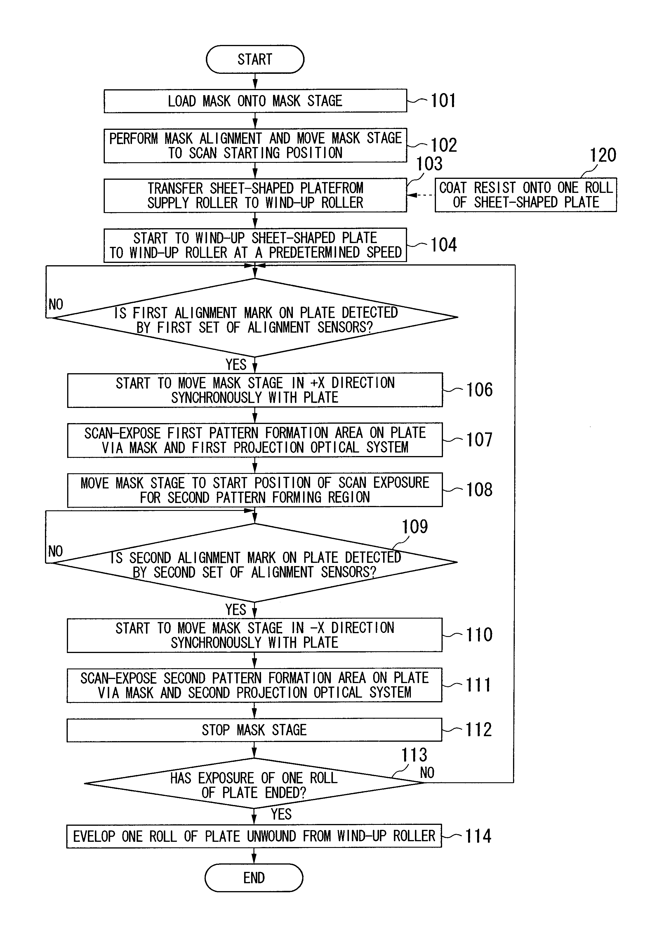
[0032]Hereinafter, a first embodiment of the invention will be described with reference to FIGS. 1 to 6.

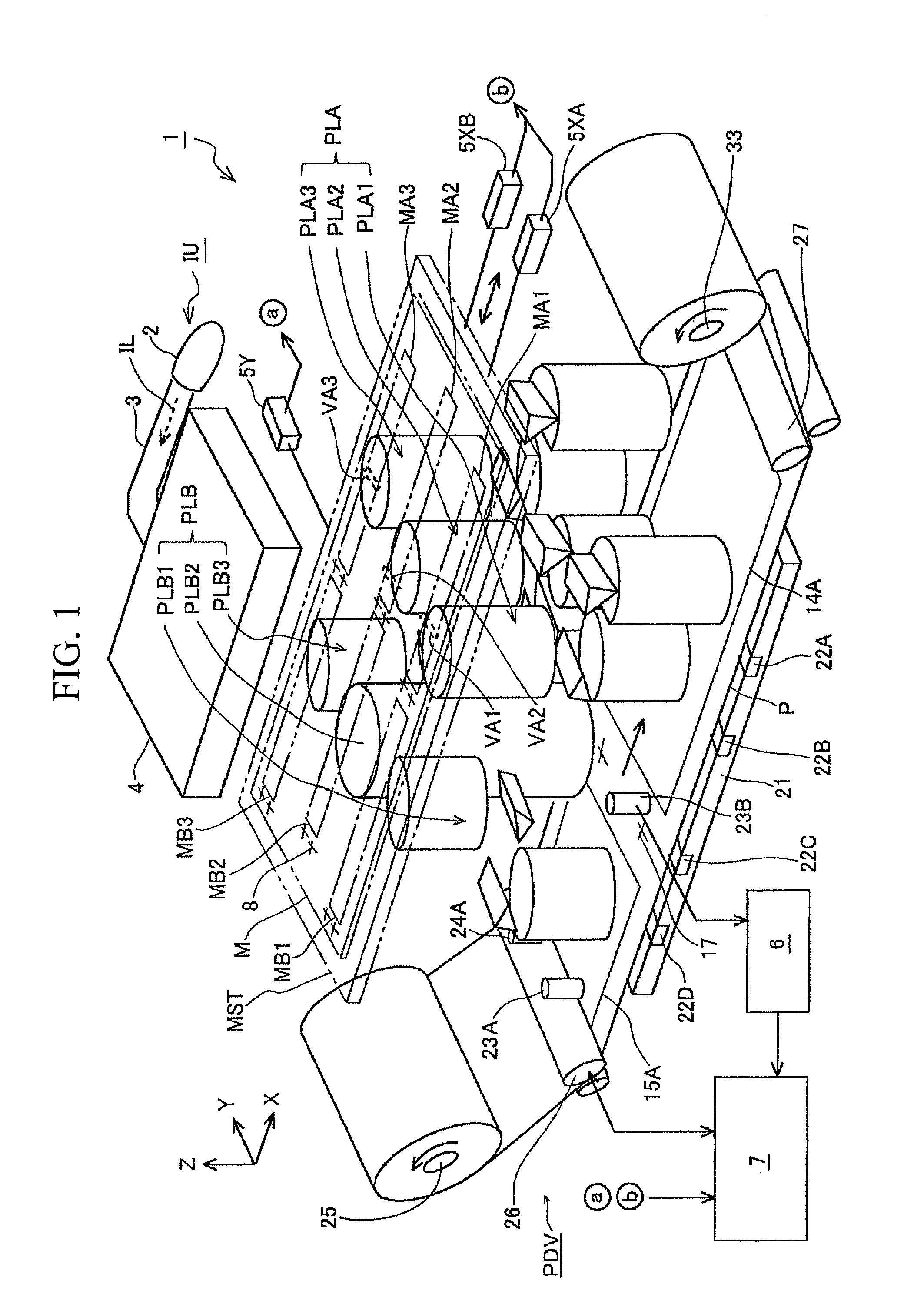
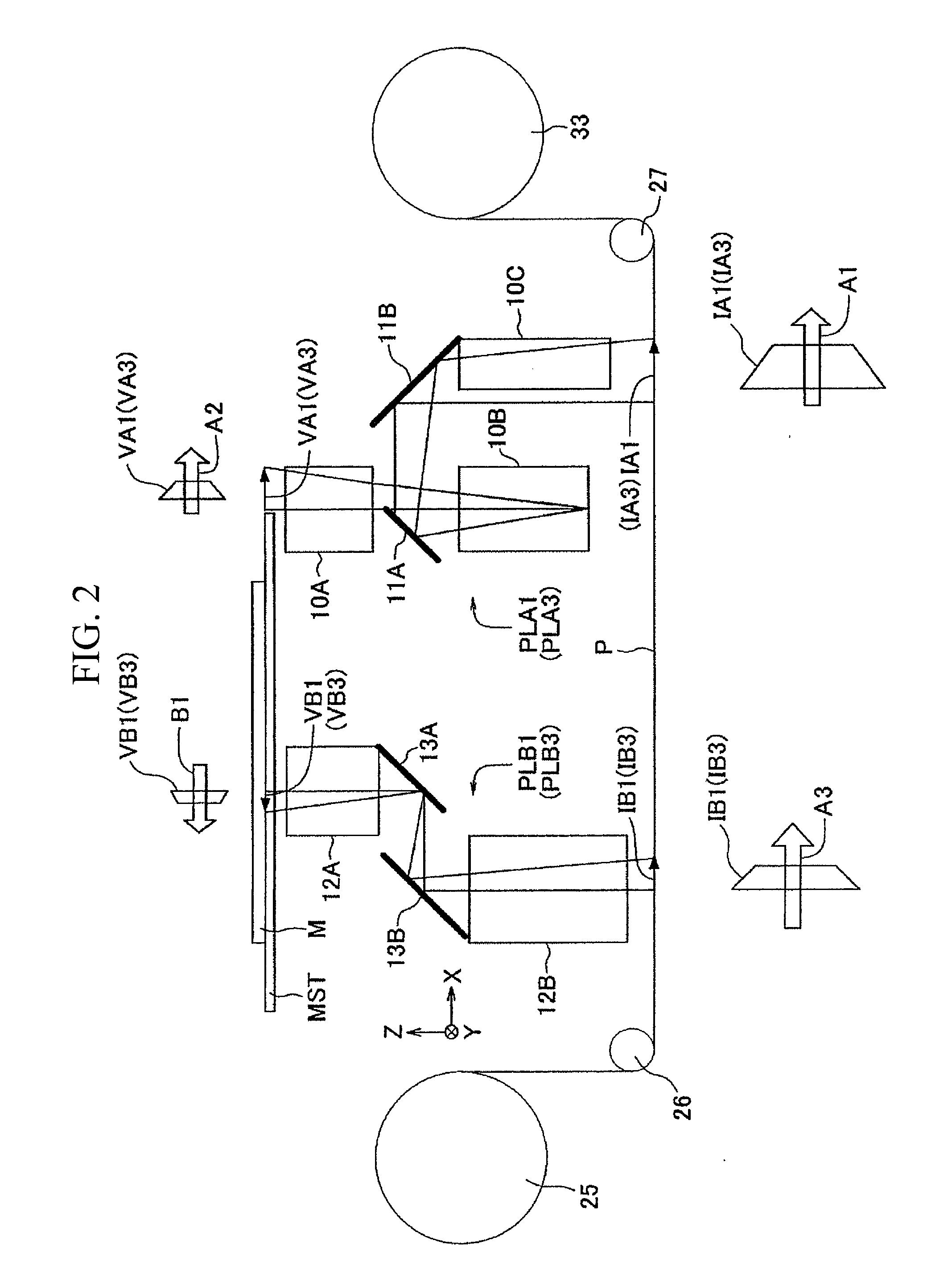
[0033]FIG. 1 shows the schematic configuration of a scan type exposure apparatus 1 (projection exposure apparatus) of this embodiment. In FIG. 1, the exposure apparatus 1 includes an exposure light source 2, an illumination unit IU which illuminates a part of a pattern of a mask M with illumination light IL (exposure light) from the exposure light source 2, a mask stage MST reciprocating while holding the mask M, and a first projection optical system PLA and a second projection optical system PLB which project an image of a part of the pattern of the mask M onto a plate P, respectively. For convenience of description, in FIG. 1, the mask M and the mask stage MST are shown in two-dot chain lines. The mask M is suctioned and held on a area of the mask stage MST including an opening. The mask stage MST is movably mounted on a mask base (not shown) having an aperture (opening) for the...

second embodiment

[0106]Next, a second embodiment of the invention will be described with reference to FIGS. 10 to 17. An exposure apparatus 1A of this embodiment is different from the exposure apparatus 1 shown in FIG. 1 in that a projection optical apparatus PL is used in which two projection optical systems PLC and PLD can be alternately switched. In FIGS. 10 to 14, the portions corresponding to FIGS. 1 to 4 are represented by the same or similar reference numerals, and detailed description thereof is omitted. The projection magnification β of the projection optical systems PLC and PLD of this embodiment is greater than or equal to 2× magnification.

[0107]FIG. 10 is a perspective view showing a main part when the exposure apparatus 1A of this embodiment uses a projection optical apparatus PL as a first projection optical system PLC. In FIG. 10, the exposure apparatus 1A includes a mask stage (not shown) which holds a mask ME and moves the mask ME in the X direction and the Y direction, an illuminat...


PUM


Abstract

An exposure method for exposing a plate with an image of a pattern of a mask comprises: reciprocating the mask along X direction, synchronizing a movement of the mask and a movement of the plate to +X direction, projecting an image of a first pattern of the mask onto the plate as an erected image with respect to +X direction during a first period in which the mask that is reciprocating is moved in +X direction, and projecting an image of a second pattern of the mask onto the plate as an inverted image with respect to +X direction during a second period in which the mask that is reciprocating is moved in −X direction.

Description

CROSS-REFERENCE TO RELATED APPLICATION[0001]This application is a non-provisional application claiming priority to and the benefit of U.S. provisional application 61 / 297,331, filed Jan. 22, 2010, and claims priority to Japanese Patent Application No. 2009-115199, filed on May 12, 2009. The contents of these applications are incorporated herein.BACKGROUND[0002]1. Field of the Invention[0003]The present invention relates to an exposure technique for exposing a substrate via a mask and a projection optical system, which is suitable for exposing a long sheet-shaped photosensitive object wound in a roll shape. In addition, the present invention relates to a fabricating technique for fabricating (manufacturing) a device using such an exposure technique.[0004]2. Description of Related Art[0005]For example, in an exposure apparatus that is used for fabricating an element such as a semiconductor element or a liquid crystal display element, a typical exposure target (exposure object) has conv...

Claims


Application Information

Patent Timeline
Patent Type & Authority Applications(United States)
IPC IPC(8): G03B27/54G03B27/58
CPCG03F7/70216G03F7/70791G03F7/70358G03F7/70275G01R27/28G03F7/20
Inventor HATADA, HITOSHI
Owner NIKON CORP
Learn More