In-vehicle network system
a technology of in-vehicle network and registration device, which is applied in the direction of digital transmission, transportation and packaging, instruments, etc., can solve the problems that cannot be ignored in terms of security, and achieve the effect of improving the processing capability of registration device, improving security, and not increasing the cost of the in-vehicle network itsel
- Summary
- Abstract
- Description
- Claims
- Application Information
AI Technical Summary
Benefits of technology
Problems solved by technology
Method used
Image
Examples
embodiment 1
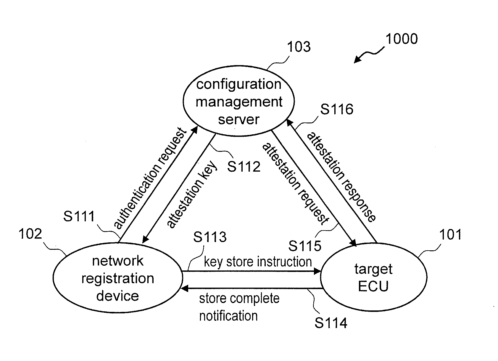
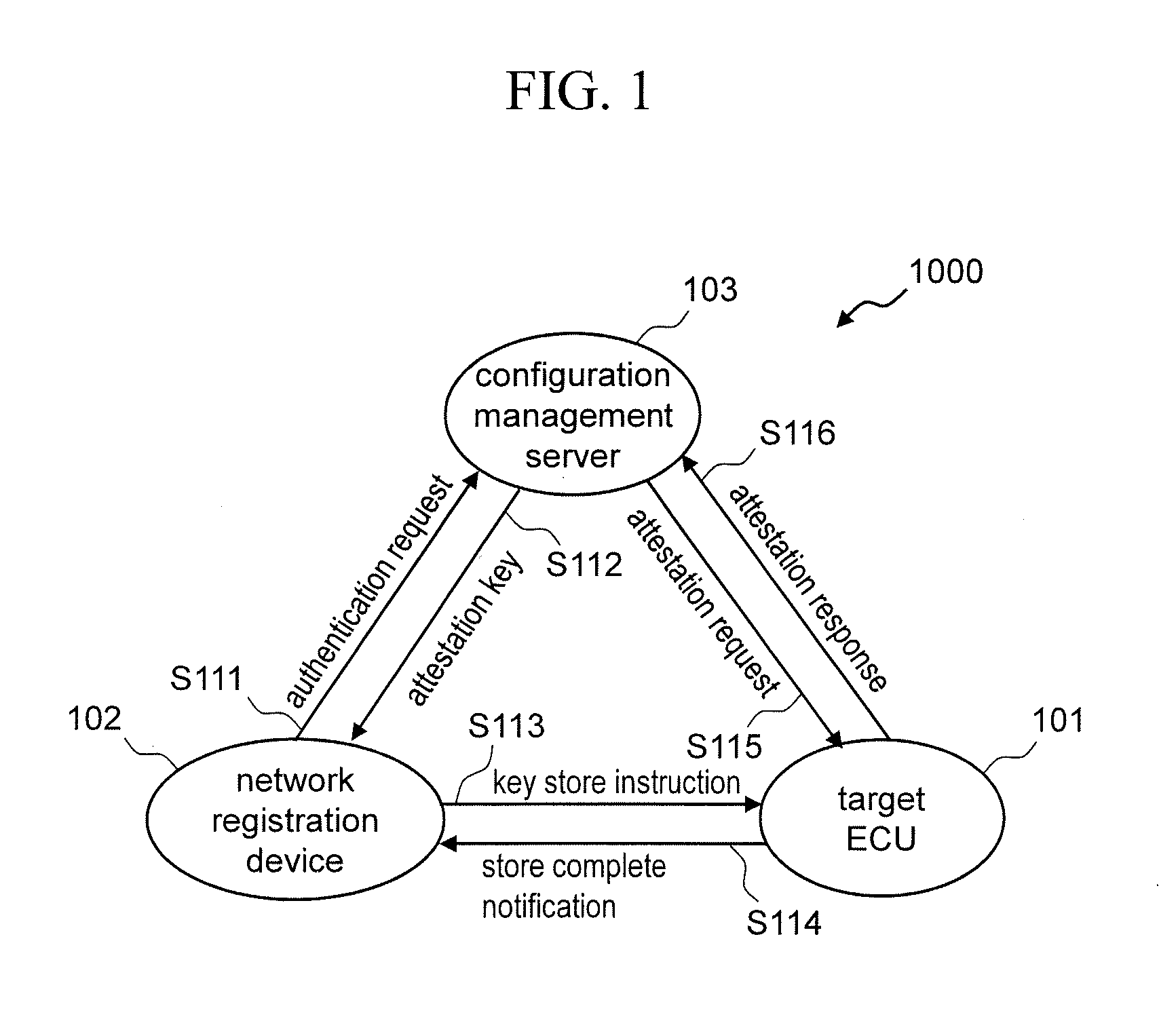
[0030]FIG. 1 is a configuration diagram of an in-vehicle network system 1000 according to the present invention. The in-vehicle network system 1000 is an in-vehicle network connecting ECUs that control car operations. Only one target ECU 101 is shown as a target of attestation in the figure. However, other ECUs may connect to the in-vehicle network system 1000.
[0031]The target ECU 101 and a configuration management server 103 are connected to the in-vehicle network system 1000 through an in-vehicle network. In addition, in order to let the target ECU 101 join the in-vehicle network, a network registration device 102 is connected to the in-vehicle network system 1000 as long as necessary.
[0032]The configuration management server 103 is a device that can communicate with the target ECU 101 and the network registration device 102 through the in-vehicle network. The configuration management server 103 may be configured as an ECU or as any type of other communication device. The configur...
embodiment 2
[0055]Hereinafter, the in-vehicle network system 1000 will be compared with the conventional example (FIG. 3) described in Patent Literature 1 to explain the difference between both configurations and securities.
[0056]FIG. 3 is a diagram showing a configuration example of the in-vehicle network described in Patent Literature 1. FIG. 3 is provided for comparison with the embodiment 2. In FIG. 3, an ECU master 105 exists in an in-vehicle network 202. The ECU master 105 has identification numbers {car ID} for each of cars.
[0057]The ECU master 105, when performing initialization process, requests the center server 203 installed at outside of the in-vehicle network 202 to distribute {common key generation source} using an information set of {car ID, ECU-ID, software version} (step S311). The ECU-ID is an identifier of the ECU master 105. The software version is a version of software equipped in the ECU master 105.
[0058]The center server 203 distributes {common key generation source} in ...
embodiment 3
[0130]As discussed thus far, in the in-vehicle network system 1000 according to the embodiment 3, the attestation is performed by the mutual authentication between the configuration management server 103 and the target ECU 101. This enables detecting that the configuration management server 103 or the target ECU 101 is falsified and an alarm indicating it can be issued.
[0131]FIG. 11 is a diagram showing an operational example in which the attestation method described in the embodiments 1-3 is applied to an application other than attestation. FIG. 11 assumes that there are two ECUs 101 (ECUs 101a and 101b) and a message with digital signature is transmitted between the ECUs.
[0132]The ECU key is shared only in the pairs of the configuration management server 103 and in-vehicle ECUs. On the other hand, the server key is shared among multiple in-vehicle ECUs. Therefore, the server key may be used to transmit a message authentication code (MAC) among multiple in-vehicle ECUs to assure th...
PUM
 Abstract
Description
Claims
Application Information
 - R&D
- Intellectual Property
- Life Sciences
- Materials
- Tech Scout
- Unparalleled Data Quality
- Higher Quality Content
- 60% Fewer Hallucinations
Browse by: Latest US Patents, China's latest patents, Technical Efficacy Thesaurus, Application Domain, Technology Topic, Popular Technical Reports.
© 2025 PatSnap. All rights reserved.Legal|Privacy policy|Modern Slavery Act Transparency Statement|Sitemap|About US| Contact US: help@patsnap.com


