Flexible printed-circuit board

a printed circuit board and flexible technology, applied in printed circuit details, cross-talk/noise/interference reduction, high-frequency circuit adaptations, etc., can solve the problems of high cost of double-sided boards, increased cost, and difficulty in transmitting signals at high speed, so as to suppress the effect of cross-talk, increase the distance of wiring pattern units, and low cost

Inactive Publication Date: 2009-01-08
PANASONIC CORP
View PDF7 Cites 22 Cited by
  • Summary
  • Abstract
  • Description
  • Claims
  • Application Information

AI Technical Summary

Benefits of technology

[0022]Since, in the wiring pattern units adjacent to each other, positive-phase and inverted-phase wiring lines of the differential signals are located adjacent to each other, increase of distance of wiring pattern

Problems solved by technology

On the other hand, there is a problem that the cost of a double-sided board is high.
However, a flexible board that can mount a plurality of connectors and prevents signal reflection and cross talk at low cost has not been proposed yet.
If a plurality of connectors are mounted on one side in a simple manner, as shown in FIG. 8, a mount area increases in response

Method used


Image

  • Flexible printed-circuit board
  • Flexible printed-circuit board
  • Flexible printed-circuit board

Examples


first embodiment

[Construction]

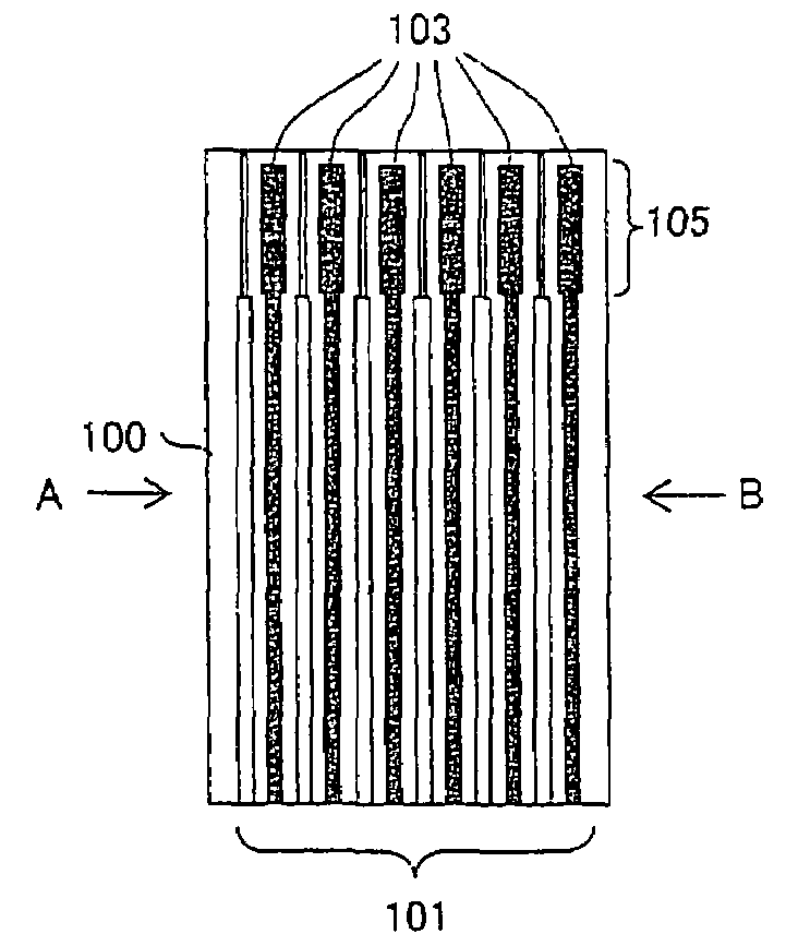
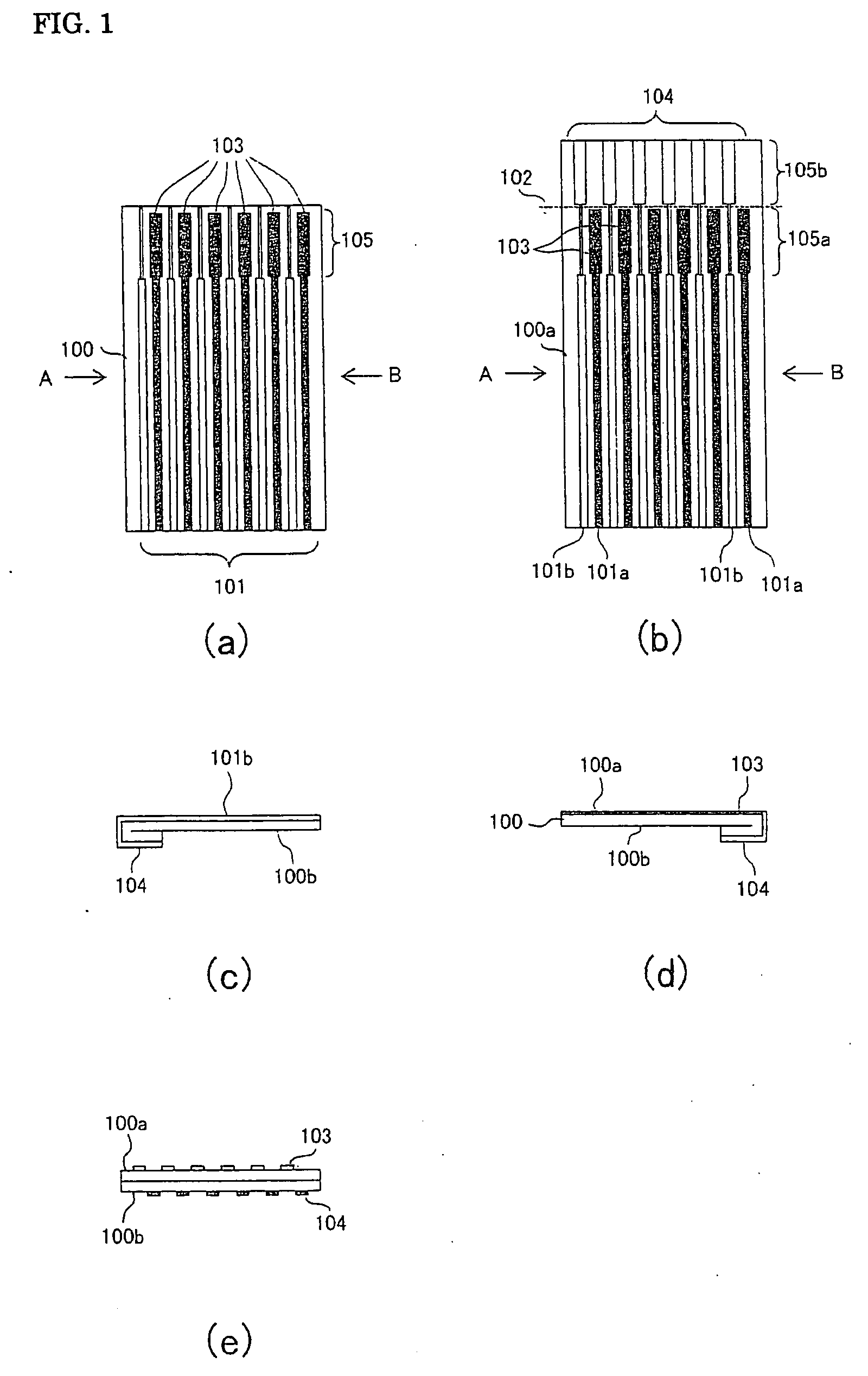
[0043]FIG. 1 shows a construction view of a flexible printed board according to a first embodiment example of the present invention. FIG. 1(a) is a plan view of the flexible printed circuit board according to this embodiment. The flexible printed board includes a body 100, wiring lines 101, and front-side pads 103. This flexible board is doubled in an overlap portion 105. The board includes back-side pads 104 (see FIGS. 1(c) and (d)) on the side of the overlap portion 105 opposite to the paper plane in the figure.

[0044]FIG. 1(b) is a plan view of the flexible printed circuit board with the overlap portion 105 being developed. The overlap portion 105 is developed to a front side 105a and a back side 105b. As discussed above, the back-side pads 104 are formed on the back side of the overlap portion 105. FIG. 1(c) is a side view of the flexible printed board when viewed from a direction A in the same Fig. (a). FIG. 1(d) is a side view of the flexible printed board when vi...

second embodiment

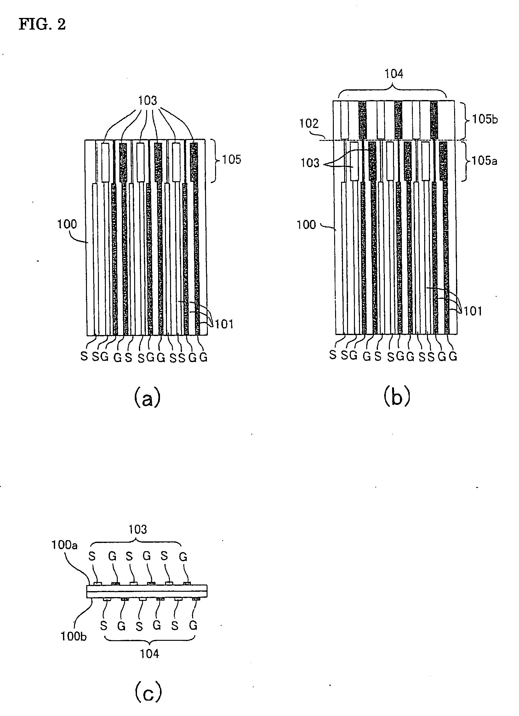
[0054]FIG. 2 shows a construction view of a flexible printed board according to a second embodiment example of the present invention. FIG. 2(a) is a plan view of the flexible printed circuit board according to this embodiment. The flexible printed board includes a body 100, wiring lines 101, and front-side pads 103. This flexible board is doubled in an overlap portion 105. The board includes back-side pads 104 (see FIGS. 2(b) and (c)) on the side of the overlap portion 105 opposite to the paper plane in the figure. FIG. 2(b) is a plan view of the flexible printed circuit board with the overlap portion 105 being developed. The overlap portion 105 is developed to a front side 105a and a back side 105b. The same Fig. (c) is a cross-sectional view of the overlap portion 105 in the same Fig. (a).

[0055]Each component is now described in detail. In the drawings, the components that is attached with the same reference numerals have construction and action similar to the foregoing first embo...

third embodiment

[0066]FIG. 3 shows a construction view of a flexible printed board according to a third embodiment of the present invention. FIG. 3(a) is a plan view of the flexible printed circuit board according to this embodiment. The flexible printed board includes a body 100, wiring lines 101, and front-side pads 103. This flexible board is doubled in an overlap portion 105. The board includes back-side pads 104 (see FIGS. 3(b) and (c)) on the side of the overlap portion 105 opposite to the paper plane in the figure. FIG. 3(b) is a plan view of the flexible printed circuit board with the overlap portion 105 being developed. The overlap portion 105 is developed to a front side 105a and a back side 105b. FIG. 3(c) is a cross-sectional view of the overlap portion 105 in the same Fig. (a).

[0067]Each component is now described in detail. In the drawings, the components that is attached with the same reference numerals have construction and action similar to the foregoing first embodiment.

(1) Body

[0...


PUM


Abstract

A flexible printed board that is adapted to high-speed transmission and can mount a plurality of connectors at low cost is provided. The board comprises a flexible printed board body 100 that has a first side 100a and a second side 100b opposed to each other, and an overlap portion 105 formed by bending its one end; a plurality of wiring lines 101 that are arranged on the first side 100a of the body substantially in parallel to each other; first pads 103 that are connected to respective ends of wiring lines, wider than the wiring lines and formed on the first-side surface 105a of the overlap potion; and second pads 104 that are located at respective ends of wiring lines, wider than the wiring lines and formed on the second-side surface 105b of the overlap potion. The wiring lines 101a with the first pads connected thereto and the wiring lines 101b with the second pads 104 connected thereto are alternatively arranged on the first side.

Description

TECHNICAL FIELD[0001]The present invention relates to a flexible printed board that is used, in computer terminals or electric devices such as AV equipment, for signal transmission.BACKGROUND ART[0002]Recently, a serial interface such as USB (Universal Serial Bus), IEEE (Institute of Electrical and Electric Engineers) 1394 is popular in computer terminals such as PC (personal computer), and electric devices such as AV equipment, and models adapted thereto has increased. Accordingly, the number of interface ports included in one electric device has increased. In addition, in an electric device, a flexible printed board that is easily routed is generally used as a transmission media for relaying signals. In terms of such a background, a flexible printed board that can transmit signals at high speed and has a plurality of connector ports is required.[0003]In order that a flexible board may transmit signals at high speed, a board with wiring provided on its both sides (double-sided boar...

Claims


Application Information

Patent Timeline
IPC IPC(8): H05K1/02
CPCH05K1/0219H05K1/0237H05K1/118H05K2201/09727H05K2201/09236H05K2201/09445H05K2201/055
Inventor SHIBATA, OSAMUNAKAYAMA, TAKESHISAITO, YOSHIYUKI
Owner PANASONIC CORP
Why Eureka
Try Eureka