
Laser projection device

Active Publication Date: 2020-09-10
ROBERT BOSCH GMBH
View PDF0 Cites 0 Cited by
  • Summary
  • Abstract
  • Description
  • Claims
  • Application Information

AI Technical Summary

Benefits of technology

The present invention relates to a laser projection device that can detect the position of its reflector element and compensate for temperature drift. The device uses a piezoelectric measuring bridge to detect the position of the reflector element, which is important for accurate projection. The device is designed to be compact, low-maintenance, and inexpensive to manufacture. The technical effects of this invention include improved accuracy and reliability of laser projection, as well as reduced cost and complexity of manufacturing.

Problems solved by technology

In particular, errors in the detected position of at least the reflector element may occur due to changes in the temperature.

Method used


Image

  • Laser projection device
  • Laser projection device
  • Laser projection device

Examples


Embodiment Construction

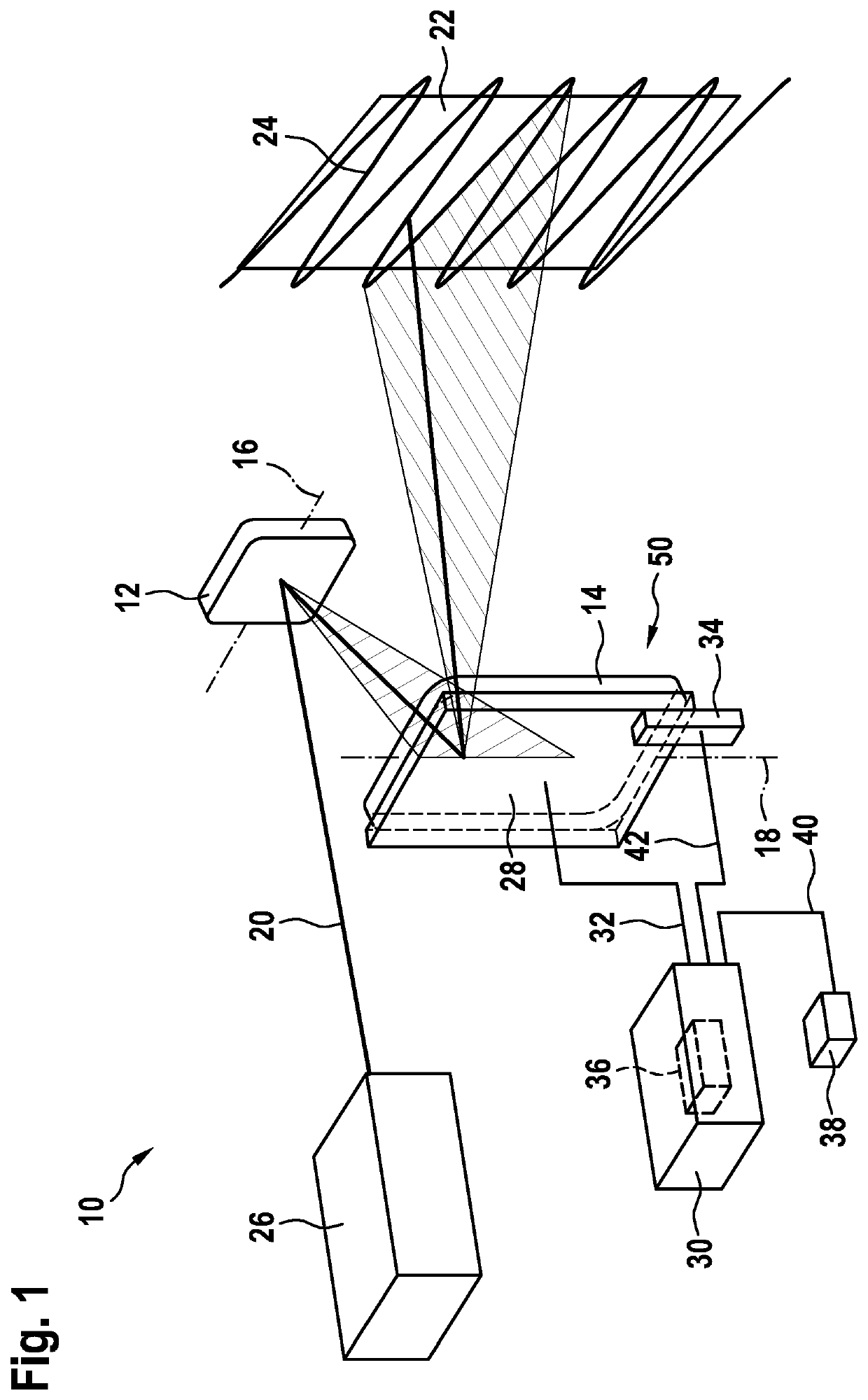
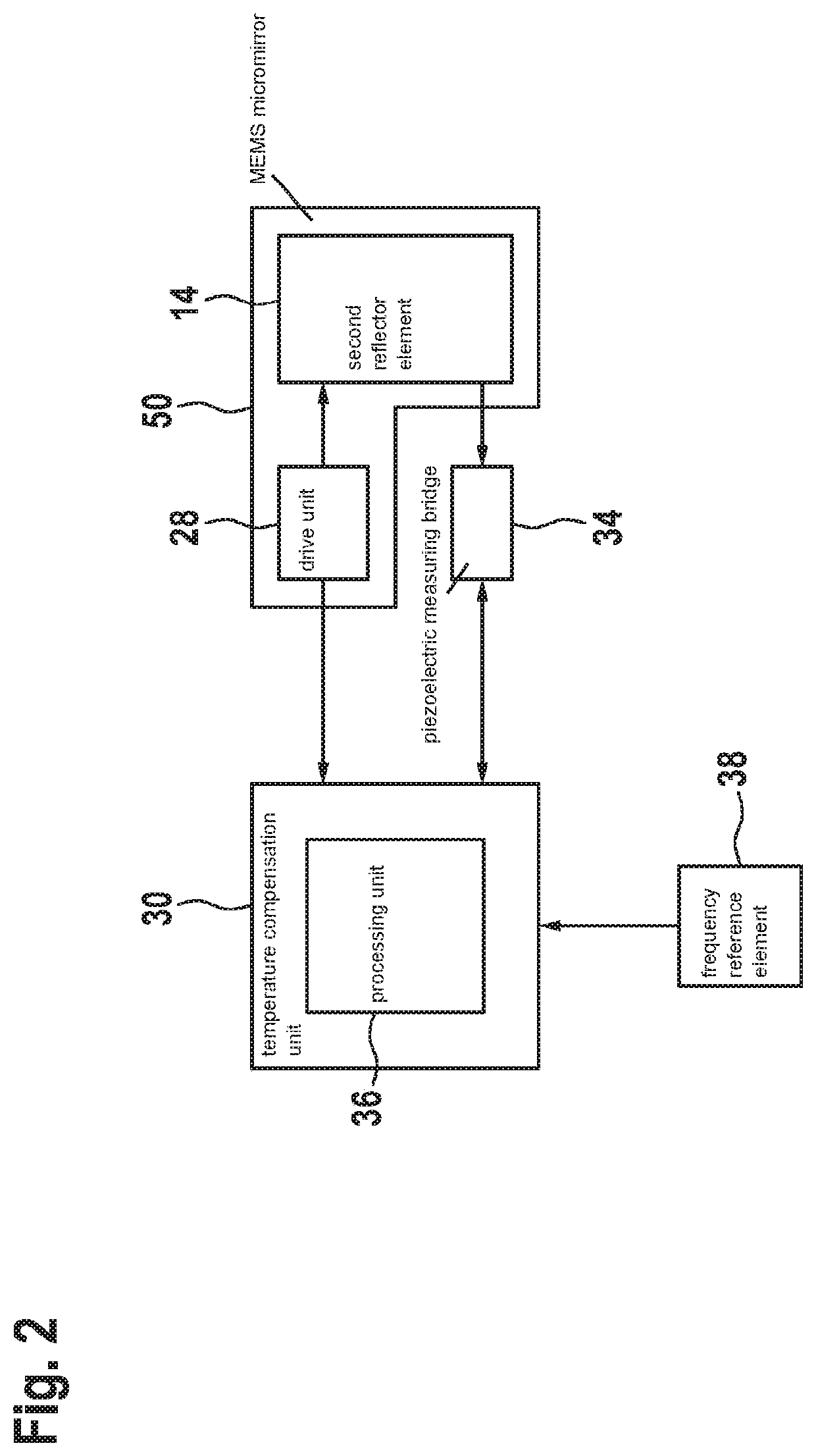
[0032]FIG. 1 shows a schematic representation of an example laser projection device 10 according to the present invention. Laser projection device 10 includes a first reflector element 12 and a second reflector element 14. First reflector element 12 takes the form of a vertical mirror and is supported so as to be movable about a first axis of rotation 16. Second reflector element 14 takes the form of a horizontal mirror and is supported so as to be movable about a second axis of rotation 18. Reflector elements 12, 14 are supported by mechanical spring systems not shown in further detail, so as to be rotatable about axes of rotation 16, 18. First axis of rotation 16 and second axis of rotation 18 are oriented substantially perpendicularly to each other. In this case, the expression “substantially perpendicularly” shall define, in particular, an orientation of first axis of rotation 16 relative to second axis of rotation 18; in particular, viewed in a plane, first axis of rotation 16 ...


PUM


Abstract

A laser projection device, including at least one reflector unit having at least one reflector element that is configured to deflect at least one laser beam to be projected, and having at least one drive unit that is configured to excite at least the reflector element into resonant vibration. The laser projection device includes at least one temperature compensation unit, which is configured to acquire a vibrational frequency of at least the reflector element and to ascertain the temperature of the reflector unit from it.

Description

BACKGROUND INFORMATION[0001]A laser projection device is already available, which includes at least one reflector unit having at least one reflector element configured to deflect at least one laser beam to be projected, and having at least one drive unit configured to excite at least the reflector element into resonant vibration.SUMMARY[0002]The present invention includes a laser projection device, which includes at least one reflector unit having at least one reflector element configured to deflect at least one laser beam to be projected, and having at least one drive unit configured to excite at least the reflector element into resonant vibration.[0003]In accordance with an example embodiment of the present invention, it is provided that the laser projection device includes at least one temperature compensation unit, which is configured to acquire a vibrational frequency of at least the reflector element and to ascertain the temperature of the reflector unit from it.[0004]A “refle...

Claims


Application Information

Patent Timeline
IPC IPC(8): G02B26/08G02B26/10
CPCG02B26/0833G02B26/101G02B26/105
Inventor EHLERT, ALEXANDERKREYE, DANIELSPECHT, HENDRIK
Owner ROBERT BOSCH GMBH
Learn More