

Control device for hybrid vehicle
- Summary
- Abstract
- Description
- Claims
- Application Information
AI Technical Summary
Benefits of technology
Problems solved by technology
Method used
Image

Examples
embodiment # 1
Embodiment #1
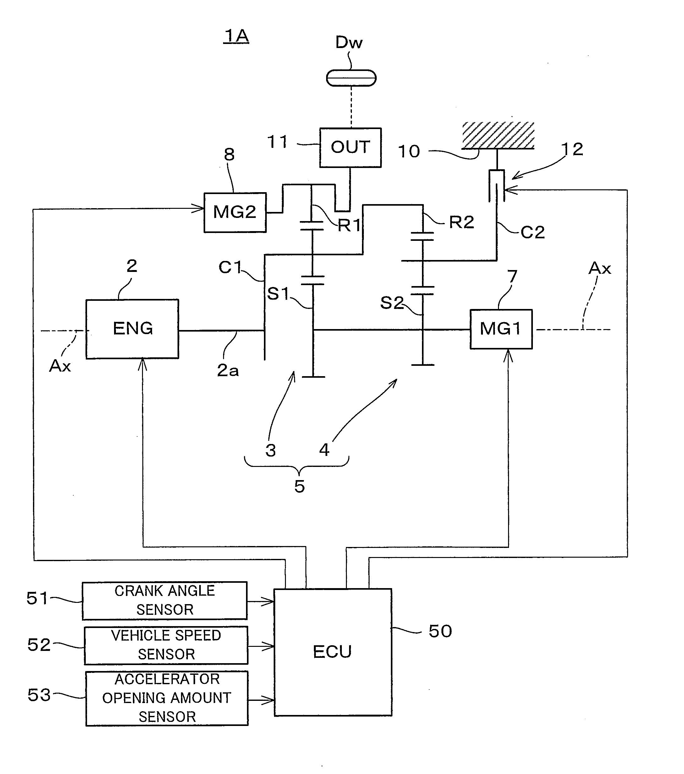
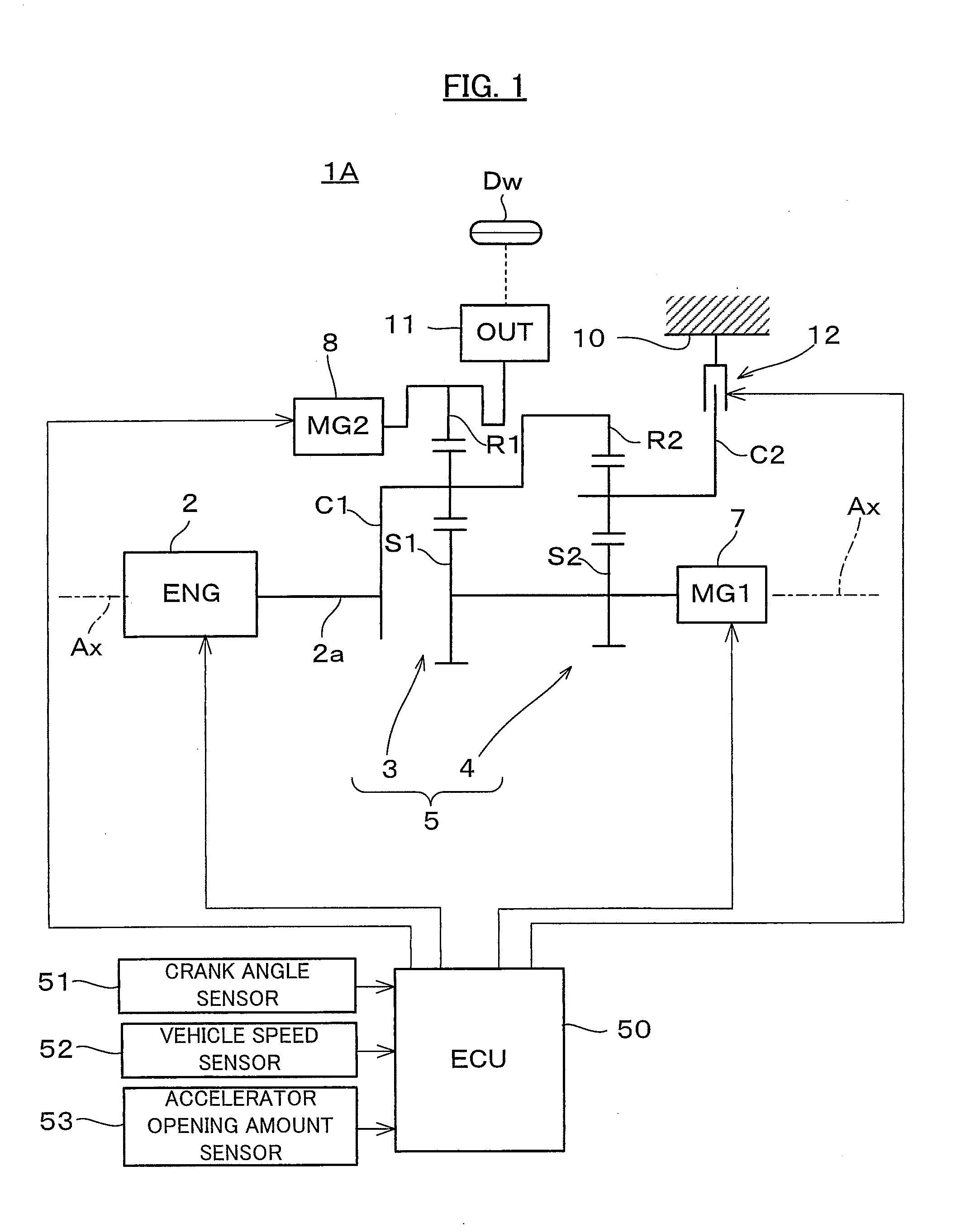
[0031]As shown in FIG. 1, a vehicle 1A is built as a hybrid vehicle to which a control device for a hybrid vehicle according to a first embodiment of the present invention is applied. This vehicle 1A comprises a spark ignition type internal combustion engine 2 which serves as an engine, a power split mechanism 5 which serves as a differential mechanism, and two motor-generators 7 and 8. The power split mechanism 5, the motor-generators 7 and 8, and power transmission elements of various kinds are received within a casing 10.
[0032]The power split mechanism 5 is built as a combination of two planetary gear mechanisms 3 and 4 which are of the single pinion type. A sun gear S1 of the first planetary gear mechanism 3 and a sun gear S2 of the second planetary gear mechanism 4 are joined together so as to rotate as a unit, and a carrier C1 of the first planetary gear mechanism 3 and a ring gear R2 of the second planetary gear mechanism 4 are joined together so as to rotate as ...
embodiment # 2
Embodiment #2
[0064]A second embodiment of the present invention will now be explained with reference to FIGS. 11 and 12. FIG. 11 is a schematic figure showing the structure of a hybrid vehicle 1B to which a control device according to this second embodiment of the present invention has been applied. This vehicle 1B differs from the vehicle 1A of the first embodiment in that it has a different structure for the power split mechanism 60, a different structure from the power split mechanism 60 to the drive wheels Dw, and a different location for mounting of the clutch 12. Since the other structural elements of this vehicle 1B are the same as corresponding ones of the vehicle 1A, accordingly the structures which are common to this vehicle 1B and the vehicle 1A will be denoted in FIG. 11 by the same reference symbols, and explanation thereof will be curtailed.
[0065]The power split mechanism 60 is built as a single pinion type planetary gear mechanism, and comprises a sun gear S which is ...
PUM
 Abstract
Description
Claims
Application Information