Laser tracking interferometer

Active Publication Date: 2014-11-27
MITUTOYO CORP
View PDF3 Cites 1 Cited by
  • Summary
  • Abstract
  • Description
  • Claims
  • Application Information

AI Technical Summary

Benefits of technology

The present disclosure is for a laser tracking interferometer that can accurately measure changes in distance, even when the housing or carriage of the interferometer is subject to thermal expansion. This allows for much more precise measurements to be made.

Problems solved by technology

Thus, when the housing of the laser interferometer 104 undergoes thermal expansion due to a change in surrounding temperature or the like, a problem arises where an error occurs in a measurement value of the amount of change ΔL.
Thus, when the carriage 102 undergoes thermal expansion due to a change in surrounding temperature or the like, a problem arises where an error occurs in a measurement value of the amount of change ΔL.

Method used


Image

  • Laser tracking interferometer
  • Laser tracking interferometer
  • Laser tracking interferometer

Examples


first embodiment

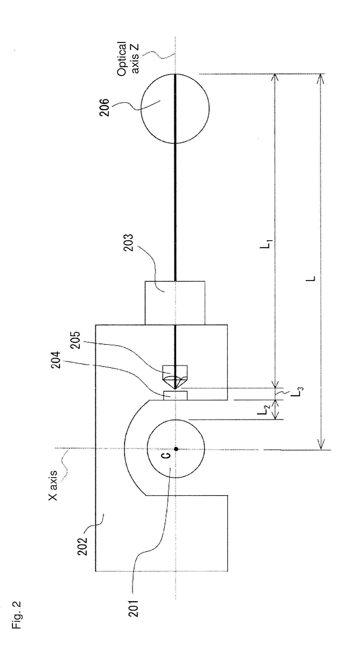
[0032]A first embodiment of the present disclosure is described with reference to FIGS. 2 to 4. FIG. 2 is a schematic diagram illustrating a configuration of a main portion of a laser tracking interferometer according to the present embodiment. FIG. 3 is a schematic diagram illustrating an internal configuration of the laser tracking interferometer according to the present embodiment. FIG. 4 is a perspective view illustrating an overall configuration of the laser tracking interferometer according to the present embodiment.

[0033]In the present embodiment shown in FIGS. 2 to 4, a first retroreflector 206 as a measured body is attached at a front end portion of a Z axis or the like of a three-dimensional measuring apparatus. A laser tacking interferometer 203 is used to track the moving first retroreflector 206, and concurrently measure an amount of change ΔL in a distance L from a center point C of a reference sphere 201 to the first retroreflector 206, the reference sphere 201 having...

second embodiment

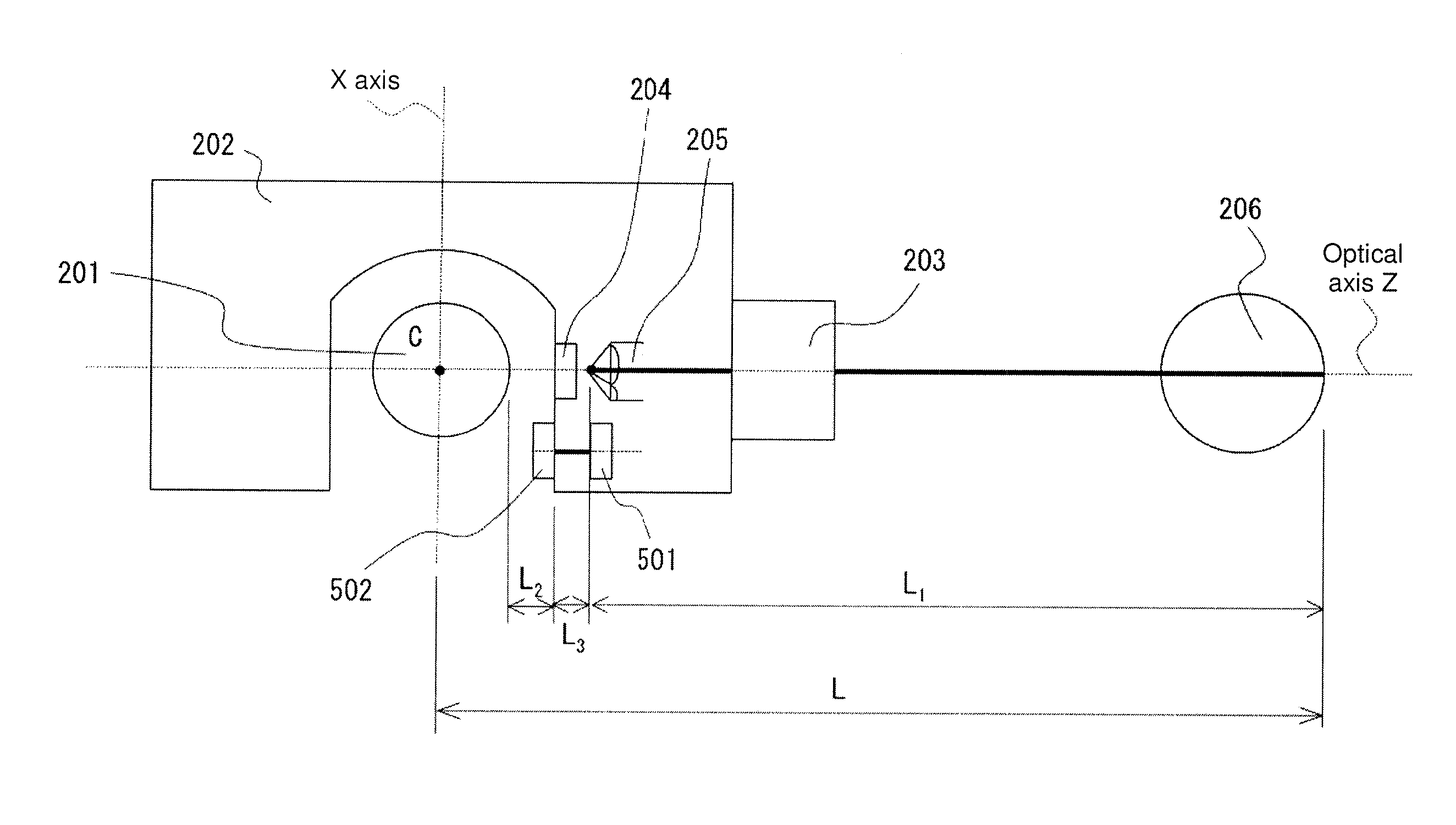
[0058]FIG. 5 is a schematic diagram illustrating a configuration of a main portion of a laser tracking interferometer according to the present embodiment. In the description below of the present embodiment, components already described are denoted with the same reference numerals and descriptions thereof are omitted or simplified. With reference to FIG. 5, the laser tracking interferometer according to the present embodiment further includes a second displacement gauge 501 and a second displacement gauge target 502, as an exemplary displacement measurer.

[0059]The second displacement gauge 501 and the second displacement gauge target 502 are fixated to the carriage 202 with a predetermined distance L3 therebetween. With reference to FIG. 5, the distance L3 is equal to a distance between a reference point of displacement measurement of the first displacement gauge 204 and the second retroreflector 205.

[0060]The second displacement gauge 501 outputs a displacement signal associated wit...

third embodiment

[0065]FIG. 6 is a schematic diagram illustrating a configuration of a main portion of a laser tracking interferometer according to the present embodiment. In the description below of the present embodiment, components already described are denoted with the same reference numerals and descriptions thereof are omitted or simplified. With reference to FIG. 6, compared to the first embodiment described above, the laser tracking interferometer according to the present embodiment further includes a third displacement gauge 601 and a holder 602, as an alternative exemplary displacement measurer.

[0066]The third displacement gauge 601 is provided on the carriage 202 between the first displacement gauge 204 and the second retroreflector 205 and is fixated to a rear surface of the first displacement gauge 204. The holder 602 is fixated to the carriage 202 so as to cover a front surface of the second retroreflector 205 which is opposite to the third displacement gauge 601. The holder 602 has a ...


PUM


Abstract

A laser tracking interferometer has a carriage provided with a first displacement gauge outputting a displacement signal associated with a relative displacement from a reference sphere; a second retroreflector provided to the carriage; a laser interferometer provided to the carriage and outputting a displacement signal associated with a relative displacement between the first retroreflector and the second retroreflector; and a data processor calculating a displacement of the first retroreflector with reference to the reference sphere based on the displacement signal output from the first displacement gauge and the displacement signal output from the laser interferometer.

Description

CROSS-REFERENCE TO RELATED APPLICATIONS[0001]The present application claims priority under 35 U.S.C. §119 of Japanese Application No. 2013-109550 filed on May 24, 2013, the disclosure of which is expressly incorporated by reference herein in its entirety.BACKGROUND OF THE INVENTION[0002]1. Field of the Invention[0003]The present invention relates to a laser tracking interferometer.[0004]2. Description of Related Art[0005]A fixed-datum type laser tracking interferometer is known (refer to U.S. Pat. No. 6,147,748, Japanese Patent No. 2603429, and Japanese Patent No. 4776454, for example), in which a first retroreflector as a measured body is attached at a front end of a Z axis or the like of a three-dimensional measuring apparatus and a laser beam is emitted toward the first retroreflector. Interference of the laser beam reflected by the first retroreflector in a return direction (direction opposite to emission) is used to measure a change in a distance from the center of a reference ...

Claims


Application Information

Patent Timeline
IPC IPC(8): G01B11/14
CPCG01B11/14G01B11/002
Inventor NARA, MASAYUKIYANAKA, SHINICHIRO
Owner MITUTOYO CORP
Why Eureka
Try Eureka