

Inkjet print head
- Summary
- Abstract
- Description
- Claims
- Application Information
AI Technical Summary
Benefits of technology
Problems solved by technology
Method used
Image

Examples
first example embodiment
Example Inkjet Print Head
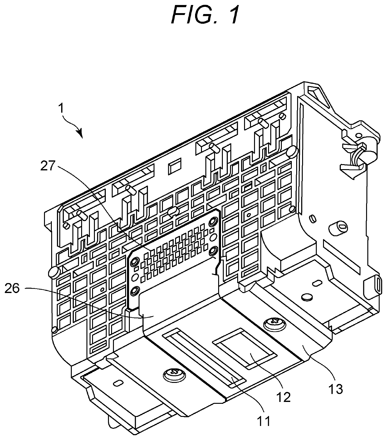
[0019]An inkjet print head according to the present embodiment will be described with reference to FIG. 1. FIG. 1 is a perspective view illustrating an inkjet print head 1 according to the present embodiment. Print element substrates 11 and 12 that eject ink are electrically connected to a flexible wiring substrate 26 in order to supply the electric power for driving a heater in the print element substrate to the print element substrates 11 and 12. The flexible wiring substrate 26 is electrically connected to an electric wiring board 27 that is electrically connected to a printing apparatus body on which the inkjet print head 1 is mounted. An ink tank that contains ink is mounted on an ink tank storage portion of the inkjet print head 1.
Example Print Element Substrate and Support Member
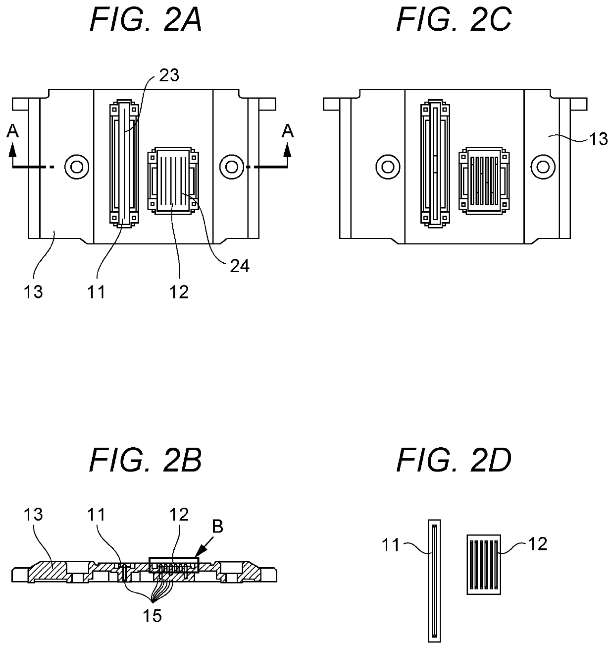
[0020]A print element substrate and a support member will be described with reference to FIGS. 2A to 4C. FIGS. 2A to 2D illustrate a print element substrate and a support memb...
example application
Height of Adhesive
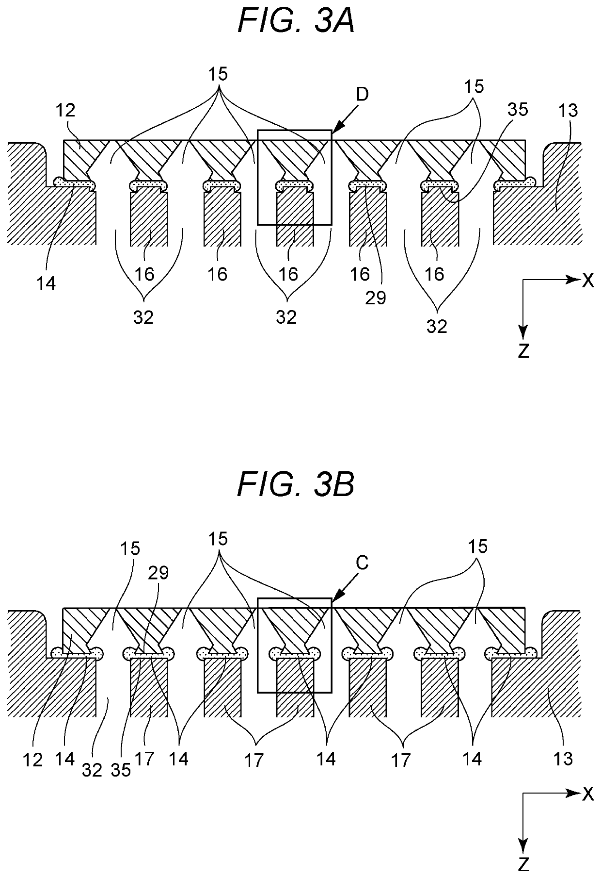
[0032]The application height 22 of the adhesive 14 applied to the adhesive surface 35 of the partition 16 illustrated in FIG. 4A-0 will be described. In the present embodiment and the second embodiment to be described below, the application height 22 of the adhesive 14 necessary for bonding the print element substrate 12 with the support member 13 is determined as follows. First, the flatness of the adhesive surface 35 of the support member 13 is 0.05 mm, the thickness of the bonding layer necessary for bonding is 0.01 mm or more, and the height for crushing the adhesive 14 with the print element substrate 12 to have sufficient bonding strength is 0.03 mm or more. The variation in the thickness of the print element substrate 12 is 0.02 mm, and the variation of the apparatus in the z direction at attaching the print element substrate 12 to the support member 13 is 0.05 mm In this case, the minimum required application height 22 of the adhesive 14 would be 0.16 mm in...
second example embodiment
[0035]A second embodiment of the present disclosure will be described with reference to FIGS. 5, 6A, and 6B. Note that portions similar to those in the first embodiment will be denoted by the same reference signs and description thereof will be omitted. FIG. 5 is a schematic view illustrating a support member 40 according to the present embodiment. FIG. 6A is a cross-sectional view illustrating a partition 39 in the B-B cross section illustrated in FIG. 5. FIG. 6B is a view illustrating a modification of the print element substrate 12 illustrated in FIG. 6A. The present embodiment is characterized in that the first portion 33 and the second portion 34 of the partition 39 are connected by a third portion 38 including a slope.
[0036]The inkjet print head 1 (refer to FIG. 1) is normally used in such a posture that the ejection port surface of the print element substrate 12 is directed downward in the vertical direction. In such a posture, providing the partition 39 with a sloped surface...
PUM
 Abstract
Description
Claims
Application Information