
Sealing member for light guide plate and planar light source device or lighting device using the same

Inactive Publication Date: 2020-11-19
TOMOEGAWA CO LTD
View PDF0 Cites 0 Cited by
  • Summary
  • Abstract
  • Description
  • Claims
  • Application Information

AI Technical Summary

Benefits of technology

The patent is about a sealing member for a light guide plate that has strong adhesion to the light guide member and prevents the guide member from getting embedded into the concave-shaped areas. This sealing member provides smoothness to the lid of the concave-shaped area. The patent also provides a light guide plate that uses this sealing member and a lighting or display device that uses this light guide plate.

Problems solved by technology

However, if the surface having the concave portions formed thereon is an outermost surface, optical properties may be lost due to attachment of a stain or a scratch.
Further, in a case of laminating with other layer, a thin air layer is inserted into a flat plane portion (a region other than the concave portions) on the surface having the concave portions formed thereon, thereby causing a problem that interference fringes or the like are generated.

Method used


Image

  • Sealing member for light guide plate and planar light source device or lighting device using the same
  • Sealing member for light guide plate and planar light source device or lighting device using the same
  • Sealing member for light guide plate and planar light source device or lighting device using the same

Examples


production example 1

[0138]Synthesis of Compound 1:

[0139]After preparing 196.29 g (1 mol) of tricyclodecanedimethanol and 22.828 g (0.2 mol) of ε-caprolactone in a flask, a temperature of them was increased to 120° C., and 50 ppm of monobutyltin oxide was added as a catalyst. Thereafter, a reaction was caused in a nitrogen gas stream until the remaining ε-caprolactone became 1% or less, which was measured by gas chromatography, thereby obtaining diol (1).

[0140]After preparing 444.56 g (2 mol) of isophorone diisocyanate in another flask, 424.57 g (1 mol) of the diol (1) was added thereto at a reaction temperature of 70° C., 232.24 g (2 mol) of 2-hydroxyethyl acrylate and 0.35 g of dibutyl tin laurylate were added when a remaining isocyanate group became 5.7%, and a reaction was continued until the remaining isocyanate group became 0.1%, thereby obtaining urethane acrylate (Compound 1), which was a monomer.

production example 2

[0141]Similarly to Production Example 1 except for changing the using amount of the ε-caprolactone from 0.2 mol to 2 mol, Compound 2, which was a monomer, was obtained (Compound 2 has a common structure with that of General Formula (Ia) in which m is 1, except that both terminals were acryloyl groups).

production example 3

[0142]Similarly to Production Example 1 except for changing the using amount of the ε-caprolactone from 0.2 mol to 1 mol, Compound 3, which was a monomer, was obtained.


PUM

PropertyMeasurementUnit
Angleaaaaaaaaaa
Angleaaaaaaaaaa
Angleaaaaaaaaaa

Abstract

A sealing member for a light guide plate which has sufficient adhesive strength with a light guide member, suppresses embedding of the light guide member into concave-shaped portions, and provides high smoothness to a lid face of the concave-shaped portions, a light guide plate using the sealing member for a light guide plate, and a lighting device or a display device using the light guide plate are provided. A sealing member for a light guide plate, which is made of one layer or more to be laminated to a face having concave portions so as to seal at least any of gas, liquid and vacuum, which has a refractive index that is different from a refractive index of a light guide member, into insides of the concave portions of the light guide member having: an emission face in which light incident from an end face is bent and outgoes to a surface direction; and the plural concave portions on the emission face and / or an opposite face that faces the emission face, wherein a layer contact with the face having the concave portions of the sealing member for a light guide plate is made of a sealing layer which contains resin composed of a repeating unit derived from urethane (meth)acrylate having a saturated cycloaliphatic group.

Description

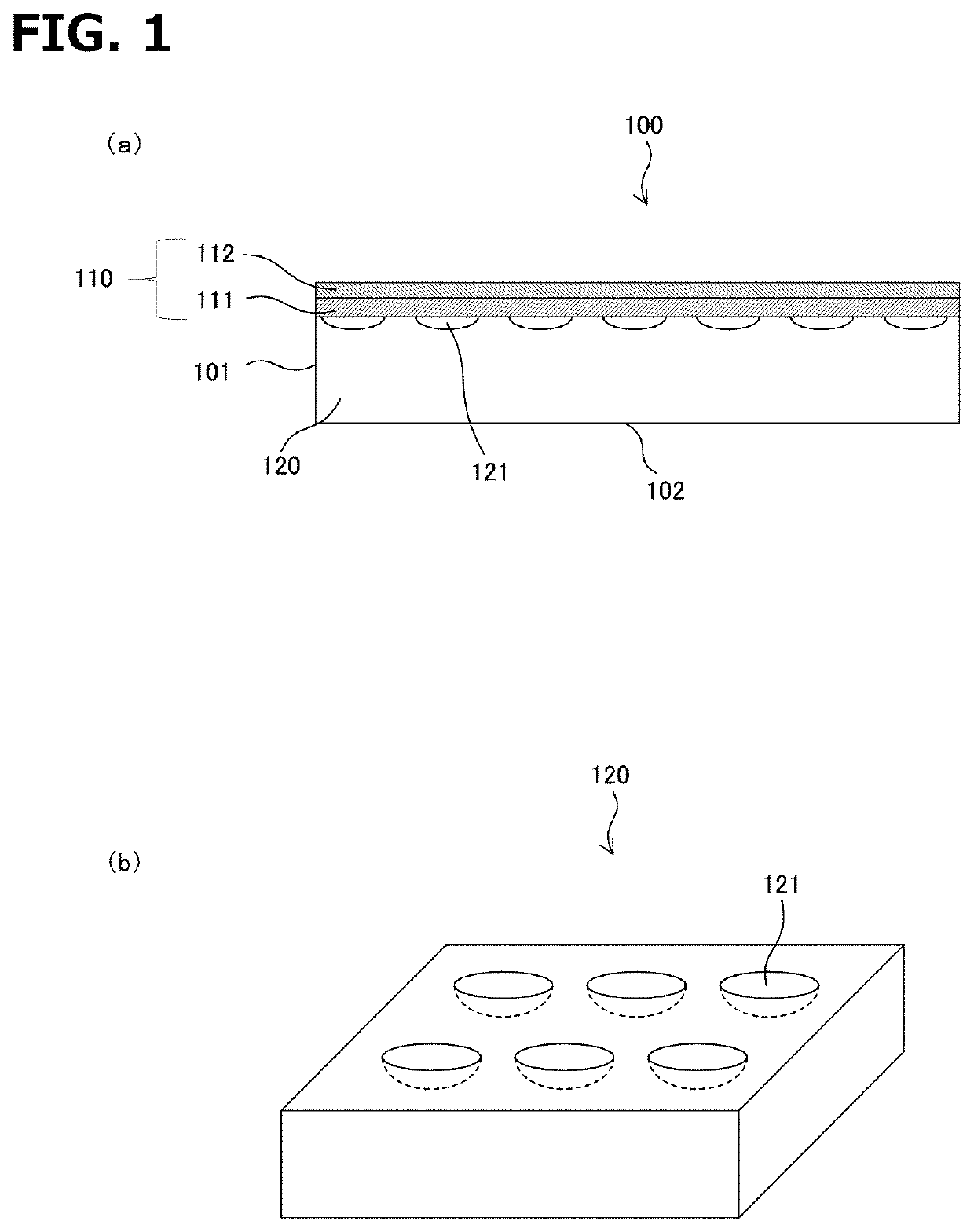
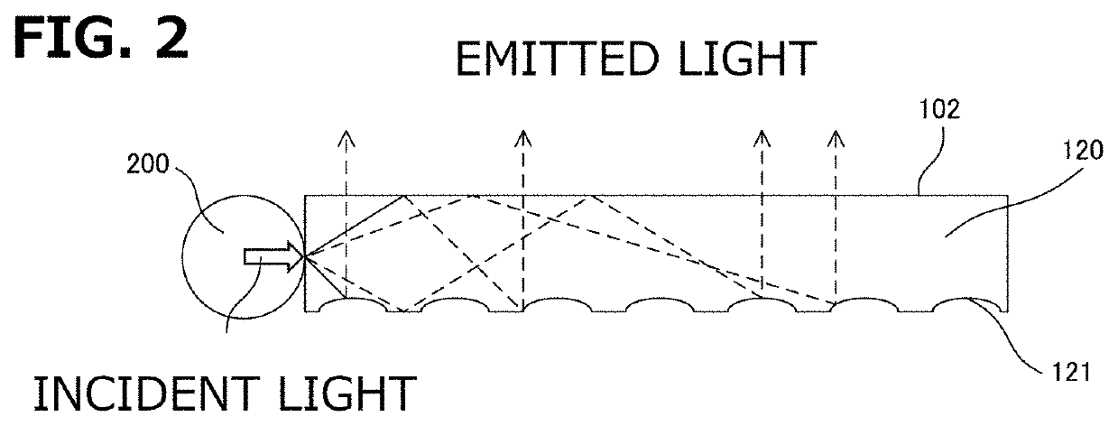
TECHNICAL FIELD[0001]The present invention relates to a sealing member for a light guide plate and a planar light source device or a lighting device which are used for an image display device such as an LCD and PDP, and for illumination of advertisements, display windows and the like.BACKGROUND ART[0002]As an aspect of a light guide plate, a light guide plate, which receives light from its end face, and reflects and refracts the light by plural concave lens shapes or dotted shapes (hereinafter, called as concave portions) formed on its surface so as to emit the light to an outside, has been known. However, if the surface having the concave portions formed thereon is an outermost surface, optical properties may be lost due to attachment of a stain or a scratch. Further, in a case of laminating with other layer, a thin air layer is inserted into a flat plane portion (a region other than the concave portions) on the surface having the concave portions formed thereon, thereby causing a ...

Claims


Application Information

Patent Timeline
IPC IPC(8): F21V8/00C08F290/06
CPCC08F290/067G02B6/0093G02B6/0036C08F290/06F21S2/00G02B1/14G02B5/02G02B6/0035C08G18/755C08G18/4277C08G18/672C08G18/73C09D175/16B32B2255/10B32B2307/748B32B2307/7242B32B27/40B32B2250/02B32B27/30B32B2307/412B32B2590/00B32B27/34B32B27/365B32B2255/26B32B27/36B32B27/285B32B2457/202B32B2307/7265B32B2307/538B32B3/30B32B2250/24B32B2457/204B32B27/08B32B27/32C08G18/42C08L33/06G02B6/10C08F220/36C08F220/343
Inventor SUGA, SHOGOKATO, MASAOSAKANO, TSUBASASUGIYAMA, MASAHIDE
Owner TOMOEGAWA CO LTD
Learn More