Seat heater and its producing method

A technology of a heating device and a manufacturing method, which can be applied to seat heating/ventilation devices, special positions of vehicles, vehicle seats, etc. Low cost, sitting comfortably, the effect of reduced quantity

Inactive Publication Date: 2008-07-02
KURABE IND CO LTD
View PDF6 Cites 0 Cited by
  • Summary
  • Abstract
  • Description
  • Claims
  • Application Information

AI Technical Summary

Problems solved by technology

[0020] On the other hand, according to the structure in which the heating wire is inserted and fixed at a position between two cloth sheets covered with adhesive (that is, the prior art as described in Patent Document 2), since it is necessary to use two supports , and there is an adhesive layer between these thin layers, so the touch will still be hard and the seating will not be good
[0021] Not only that, this type of seat heating requires many parts, and since the thin layer of cloth covered with adhesive is very expensive, the cost of the product will also increase considerably

Method used


Image

  • Seat heater and its producing method
  • Seat heater and its producing method
  • Seat heater and its producing method

Examples


no. 1 example

[0078] now refer to Figures 1 to 6 A first embodiment of the present invention will be described. The example described in the first embodiment assumes that the present invention is applied to a seat heating device for a vehicle.

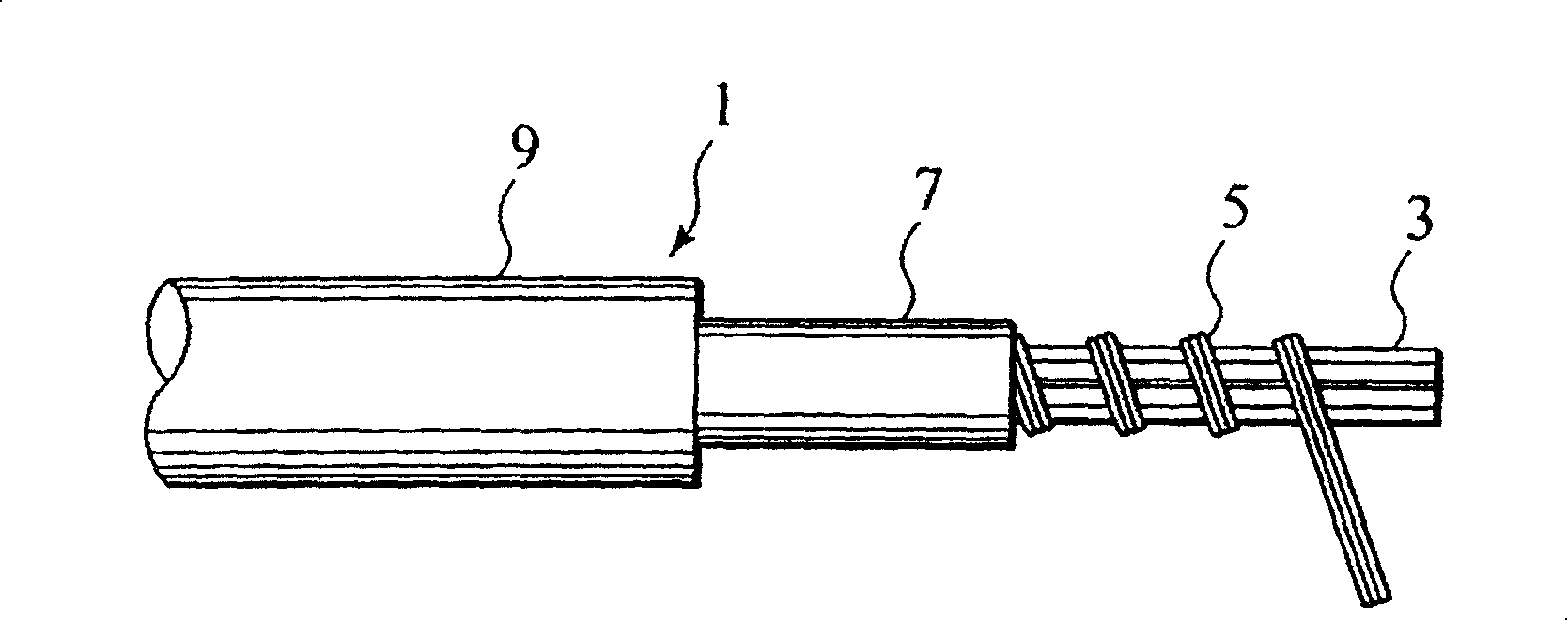
[0079] now refer to figure 1 The structure of a heating wire 1 according to the first embodiment of the present invention will be described. The heating wire 1 includes a core wire 3 of a heating element made of a bundle of aromatic polyamide, with an outer diameter of about 0.2 mm; The helical spacing is about 0.7 mm. The heating element 5 includes six parallel heating wires, each of which has an outer diameter of about 0.08 mm and is made of tin-plated copper-tin alloy (TH-SNCC-3). The outer periphery of the above-mentioned heating element 5 is covered with an extruded insulating layer 7 with a thickness of about 0.15 mm, which is made of a copolymer of tetrafluoroethylene and hexafluoropropane (FEP). In addition, the outer periphery of the...

no. 2 example

[0108] now refer to Figure 7 A second embodiment of the present invention will be described. According to the first embodiment described above as an example showing the basic structure of the heating wire, a heating element is provided in which a plurality of parallel heating wires are wound on the outer periphery of the core wire of the heating element. However, the invention is of course not limited to this first embodiment.

[0109] For example, according to the second embodiment, the present invention can also be applied to a system such as Figure 7 A so-called "high tensile strength type" heating wire 51 is shown. It will be described in detail below.

[0110] The structure of the heating wire 51 will now be described according to the second embodiment. It has a core wire 53 made of a bundle of aromatic polyamide fibers and a heating element 55 wound helically on the outer periphery of the core wire 53 of the heating element. The heating element 55 is in the form o...

no. 3 example

[0113] now refer to Figure 8 A third embodiment of the present invention will be described. Figure 8 Shown is a so-called "single wire" heater wire 61 configuration. As in the case of the first and second embodiments, the present invention can also be applied to this type of heating wire 61 .

[0114] The structure of the heating wire 61 will now be described according to the third embodiment. It has a heating element core wire 63 made of glass fiber or polyester fiber and a heating element 65 helically wound on the outer periphery of the heating element core wire 63 . The heating body 65 includes a heating wire.

[0115] The heating element 65 may also include a plurality of heating wires.

[0116] The outer periphery of the heat generating body 65 is covered with an extruded fusion layer 67 made of polyester-based resin such as nylon-11 or nylon-12. In addition, a nickel wire 69 is helically wound on the outer periphery of the fusion layer 67 to be used as a heat dete...


PUM


Abstract

To provide a seat heater and the manufacturing method thereof, having the stable adherent strength between the heating wire and the base cloth for a long time, with a good seat feeling, at a lower cost. The seat heater is comprising, a base cloth mixed with heat bonding filament, and a heating wire having a heat bonding layer and being placed in a predetermined pattern shape, in order to adhere to and be fixed on the base cloth by heat bonding under heat and pressure. Thus the stable adherent strength between the heating wire and the base cloth may be maintained for a long time, with a good seat feeling, at a lower cost.

Description

technical field [0001] The present invention relates to a seat heating device that can be used, for example, in a vehicle seat, and a method for its manufacture. More specifically, the present invention relates to a seat heating device in which a heating wire is provided on a base cloth, so that sufficient and stable adhesion strength between the heating wire and the base cloth can be maintained for a long period of time and can be made at a low cost. Get a good sitting feeling at a low cost. Background technique [0002] There are several conventional seat heating devices in which, for example, a coiled (zigzag) heating wire is placed on a sewable support such as cloth so that the heating wire can pass through the upper and lower wires. The thread is sewn and fixed to the cloth (for example, refer to Patent Document 1); or in the heating device, a wound (zigzag) heating wire is placed on a support such as cloth, and then clamped to the surface covering Between two thin cl...

Claims


Application Information

Patent Timeline
Patent Type & Authority Patents(China)
IPC IPC(8): B60N2/56
CPCB60N2/5685B60N2/5628B60N2/5635B60N2/565
Inventor 石山友一斋藤雅嗣长谷康浩小出修
Owner KURABE IND CO LTD
Why Eureka
Try Eureka