Check patentability & draft patents in minutes with Patsnap Eureka AI!

Inkjet recording device

a recording device and inkjet technology, applied in the direction of printing, instruments, other printing devices, etc., can solve the problems of misrecognition and unusable information, and achieve the effect of appropriate resolution

Inactive Publication Date: 2020-09-17
KONICA MINOLTA INC
View PDF0 Cites 0 Cited by
  • Summary
  • Abstract
  • Description
  • Claims
  • Application Information

AI Technical Summary

Benefits of technology

The inkjet recording device can produce images with higher resolution using this invention.

Problems solved by technology

However, if the resolution of the image reading device is lower than structures characteristic of a test image, such as an interval of strips, artificial structures, such as moire, may appear in imaging data, and accordingly necessary information may not be obtained, or misrecognition may occur.

Method used


Image

  • Inkjet recording device
  • Inkjet recording device
  • Inkjet recording device

Examples


Embodiment Construction

[0041]Hereinafter, one or more embodiments of the present invention are described on the basis of the drawings.

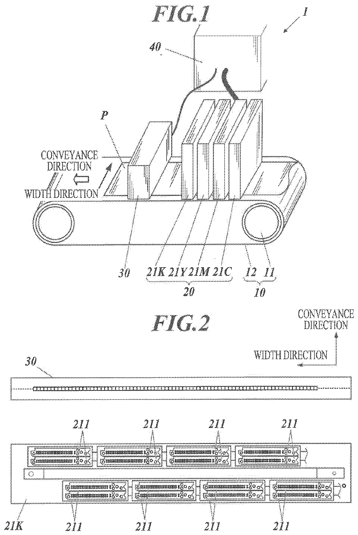
[0042]FIG. 1 is a perspective view showing the whole inkjet recording device 1 according to an embodiment(s) of the present invention.

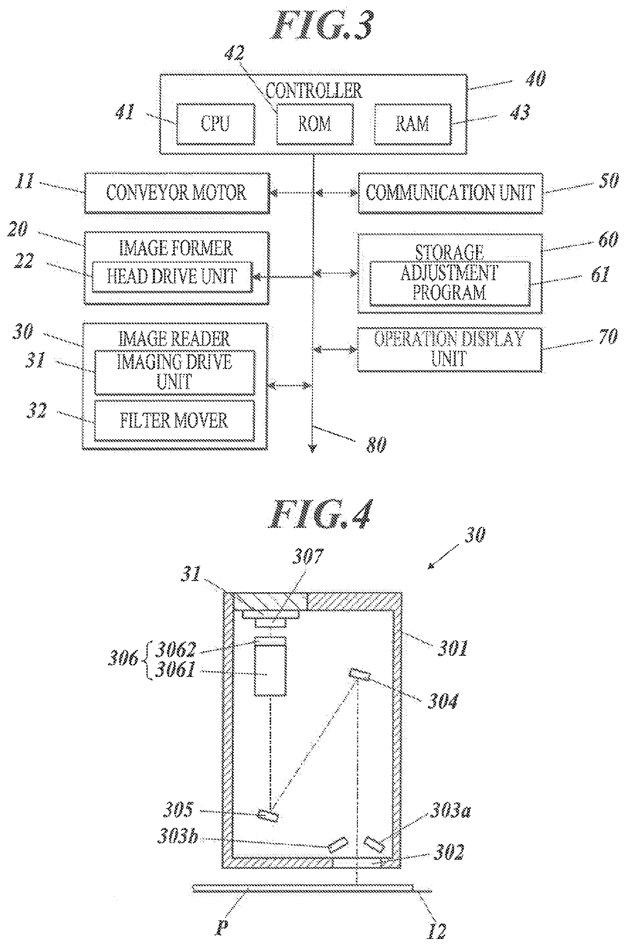
[0043]The inkjet recording device 1 includes a conveyor 10 (moving unit), an image former 20 (recording unit), an image reader 30 (imaging unit), and a controller 40 (a movement control unit, a position information obtaining unit, a filter control unit).

[0044]The conveyor 10 has a conveyor motor 11, a conveyor belt 12 and so forth, and moves, as a conveyance surface, the outer circumferential surface of the conveyor belt 12 in a predetermined conveyance direction (relative movement direction) in relation to the image former 20, thereby moving a recording medium P placed on the conveyance surface in the conveyance direction.

[0045]The image reader 30 is arranged on the downstream side of the image former 20 in the conveyance direction of the re...


PUM

PropertyMeasurementUnit
frequencyaaaaaaaaaa
cutoff frequencyaaaaaaaaaa
Nyquist frequencyaaaaaaaaaa

Abstract

An inkjet recording device includes: an image former; an image reader including a line sensor and an optical unit; and a conveyor. The line sensor has imaging elements, and detects incident light from a surface of a recording medium over an imaging range corresponding to arrangement of the imaging elements in a width direction intersecting a relative movement direction in which the recording medium and / or the image reader is relatively moved, thereby performing one-dimensional imaging along the width direction. The optical unit removes a high-frequency-side component that is a spatial structure equal to or higher than a predetermined cutoff frequency from spatial distribution of the incident light from the imaging range and guides the incident light to the line sensor. The cutoff frequency for the high-frequency-side component is determined to be lower in the width direction than the relative movement direction.

Description

TECHNICAL FIELD[0001]The present invention relates to an inkjet recording device.BACKGROUND ART[0002]There is a conventional inkjet recording device which forms images by discharging ink from a plurality of nozzles. Nowadays, with demands on speedup and accuracy increase in image forming, the number of nozzles has being increasing. There is also an inkjet recording device using a line head(s) which performs image forming at high speed by forming images while conveying recording media in a predetermined conveyance direction without moving nozzles arranged to cover the width of the recording media.[0003]Inkjet recording devices need to discharge ink from each of nozzles normally. Even if ink is discharged from each of nozzles normally, variation in, for example, drive units which drive loads for discharging the ink from the nozzles needs to be adjusted. Further, if a plurality of recording heads is arranged to discharge ink from their nozzles, relative positions of the recording heads...

Claims


Application Information

Patent Timeline
Patent Type & Authority Applications(United States)
IPC IPC(8): B41J29/393
CPCB41J2029/3935B41J29/393B41J2/01B41J29/38H04N1/00002H04N1/00007H04N1/00015H04N1/00042H04N1/00074B41J2/2146B41J2/2135G06K15/027G01N21/8901
Inventor DATE, MASAKAZUMIZUTANI, TOSHIYUKI
Owner KONICA MINOLTA INC
Features
  • R&D
  • Intellectual Property
  • Life Sciences
  • Materials
  • Tech Scout
  • Unparalleled Data Quality
  • Higher Quality Content
  • 60% Fewer Hallucinations
Learn More