Power circuit switching device having a passive protection circuit
- Summary
- Abstract
- Description
- Claims
- Application Information
AI Technical Summary
Benefits of technology
Problems solved by technology
Method used
Image
Examples
Embodiment Construction
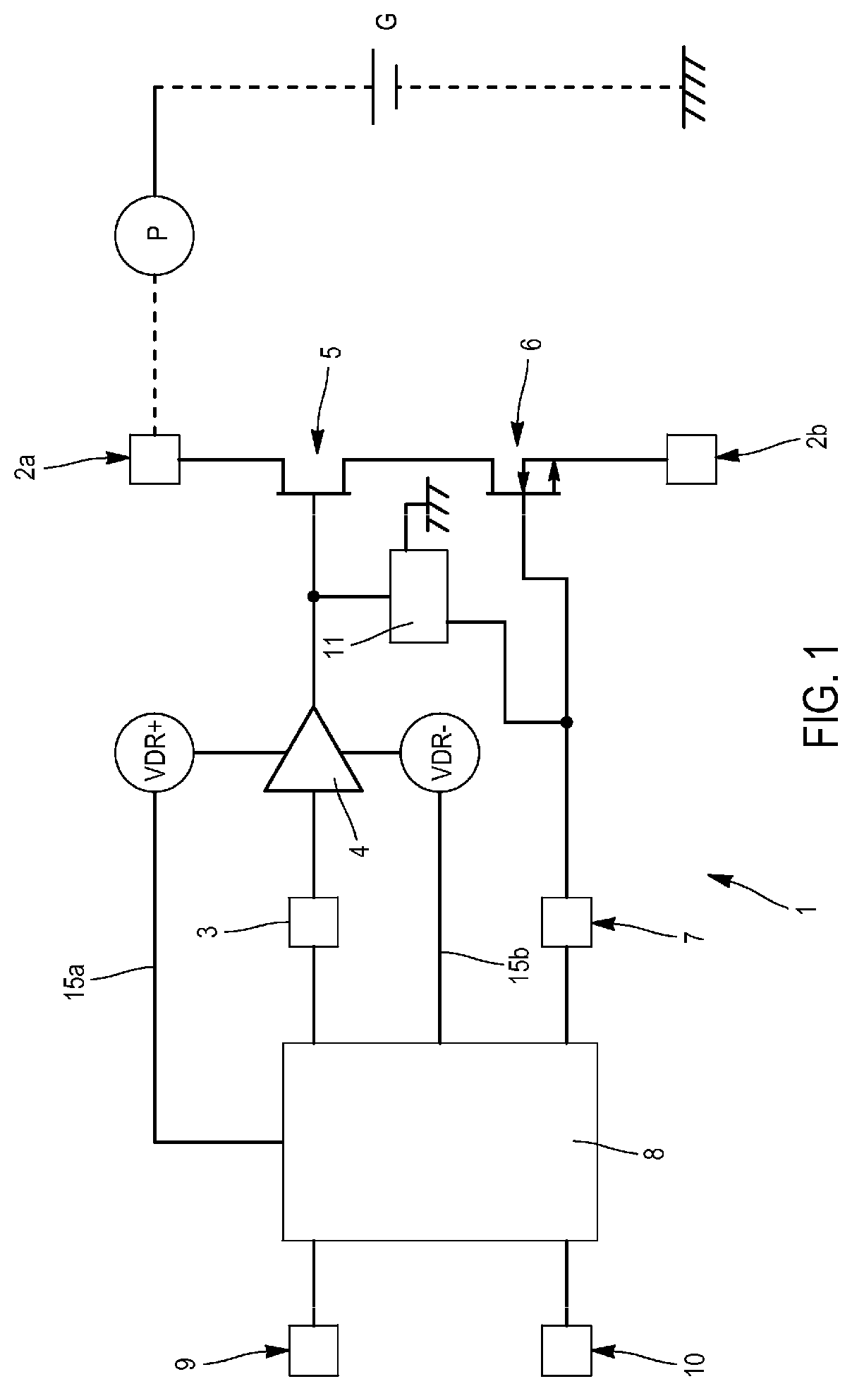
[0029]FIG. 1 shows a switching device 1 according to the disclosure. A load P and a generator G of a power circuit connected to two switching terminals 2a, 2b of the device 1 are shown in dotted lines in this figure.
[0030]The generator G can have a high voltage, for example, 600V or more, and the current flowing in the power circuit and in the switching device 1 can be of high intensity, for example, above 1 A. The switching device 1, as is well known per se, selectively applies the generator G voltage to the load P. It therefore acts as a power switch, controlled by a relatively small switching signal of the order of a few volts.
[0031]The switching device 1 has a first terminal 3 for receiving this switching signal. This first terminal 3 is electrically connected via a driver circuit 4 to a gate of a high-voltage depletion mode transistor 5.
[0032]“High-voltage transistor” means a transistor comprising a drain, a source and a gate, the low amplitude voltage applied to the gate (of t...
PUM
 Abstract
Description
Claims
Application Information
 - R&D
- Intellectual Property
- Life Sciences
- Materials
- Tech Scout
- Unparalleled Data Quality
- Higher Quality Content
- 60% Fewer Hallucinations
Browse by: Latest US Patents, China's latest patents, Technical Efficacy Thesaurus, Application Domain, Technology Topic, Popular Technical Reports.
© 2025 PatSnap. All rights reserved.Legal|Privacy policy|Modern Slavery Act Transparency Statement|Sitemap|About US| Contact US: help@patsnap.com


