Power transmission device for four-wheel drive vehicle

a technology of transmission device and four-wheel drive vehicle, which is applied in the direction of electric propulsion mounting, vehicle sub-unit features, jet propulsion mounting, etc., can solve the problem that the propeller shaft cannot be disposed in the floor tunnel

Active Publication Date: 2020-09-24
NISSAN MOTOR CO LTD
View PDF0 Cites 1 Cited by
  • Summary
  • Abstract
  • Description
  • Claims
  • Application Information

AI Technical Summary

Benefits of technology

[0006]In view of the problem described above, the object of the present disclosure is to make it possible to locate the transfer output shaft at essentially the center in the vehicle width direction and to avoid the inability to locate the propeller shaft in the floor tunnel.
[0008]In this manner, by setting the transfer case output to the rear side of the gear case by wrapping around from the side surface to the rear surface of the gear case, as seen from above, it is possible to position the transfer output shaft at essentially the center position in the vehicle width direction, and to avoid the inability of locating the propeller shaft in the floor tunnel.

Problems solved by technology

Therefore, if the transfer case is arranged in the same manner as in the conventional device, the location of the transfer output shaft shifts from the center in the vehicle width direction, which creates the problem that the propeller shaft cannot be disposed in the floor tunnel.

Method used


Image

  • Power transmission device for four-wheel drive vehicle
  • Power transmission device for four-wheel drive vehicle
  • Power transmission device for four-wheel drive vehicle

Examples


first embodiment

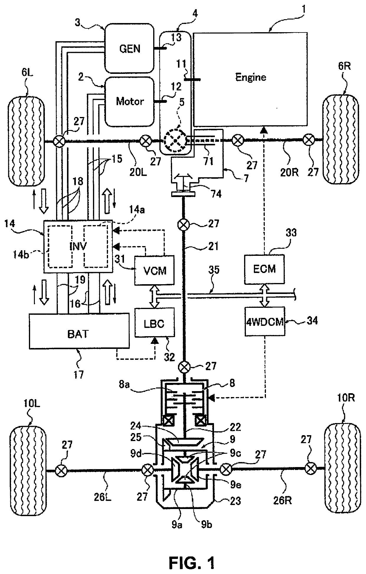
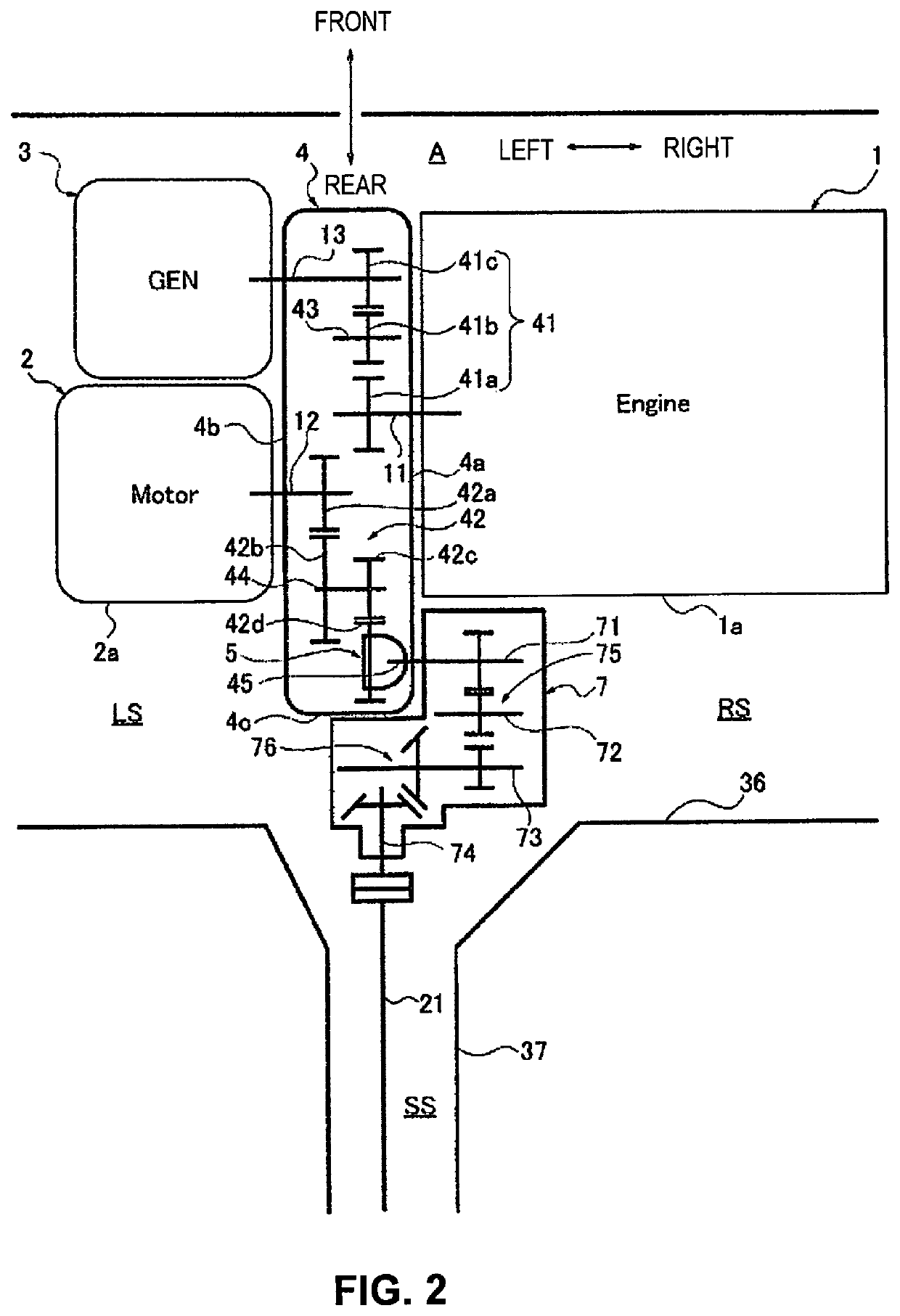
[0023]The configuration is described first. The power transmission device according to the first embodiment is applied to an FF-based four-wheel drive electrically driven vehicle (one example of a four-wheel drive vehicle) that has an engine as a power source for power generation and a motor as a power source for traveling, and that uses the electrical power generated by the engine to drive the motor. The “overall system configuration,” the “layout configuration of the front-side power transmission system” the “detailed configuration of the gear case,” and the “detailed configuration of the transfer case” will be separately described below with respect to the configuration of the first embodiment.

Overall System Configuration

[0024]FIG. 1 illustrates an FF-based four-wheel drive electrically driven vehicle to which the power transmission device according to the first embodiment is applied. The overall system configuration of the four-wheel drive electrically driven vehicle will be des...

second embodiment

[0100]The second embodiment is an example in which the transfer case wraps around from the side surface of the two side surfaces of the gear case which is opposite the side surface on which the engine is supported, to the rear surface of the gear case, as seen from above, and outputs power to the auxiliary drive wheels from the rear surface side of the gear case.

[0101]The configuration is described first. The “overall system configuration” and the “detailed configuration of the gear case” are the same configurations as the first embodiment, except that the side surface of the gear case on which the transfer case is supported is opposite to that of the first embodiment, so that illustrations and descriptions thereof are omitted. The “layout configuration of front-side power transmission system” and the “detailed configuration of transfer case” of the second embodiment will be described below.

Layout Configuration of the Front-Side Power Transmission System

[0102]FIG. 11 shows a layout ...


PUM


Abstract

A power transmission device of a four-wheel drive electrically driven vehicle comprises a transverse engine that is supported on one right side surface of two side surfaces of the gear case, and a motor that is supported on the other left side surface of the two side surfaces of the gear case. The power transmission device includes a transfer case that is supported by a gear case and the distributes power from a power source between the left and right front wheels and the left and right rear wheels. The transfer case wraps around from the side surface to a rear surface of the gear case, as seen from above, and outputs power to the left and right rear wheels from the rear surface side of the gear case.

Description

CROSS-REFERENCE TO RELATED APPLICATIONS[0001]This application is a U.S. national stage application of International Application No. PCT / JP2017 / 038274, filed on Oct. 24, 2017.BACKGROUNDTechnical Field[0002]The present disclosure relates to a power transmission device of a four-wheel drive vehicle comprising a transfer case that is supported by a gear case and that distributes power from a power source to the main drive wheels and the auxiliary drive wheels.Background Information[0003]A power transmission structure of a four-wheel drive vehicle equipped with a transfer case (the power distribution mechanism 1) that is mechanically connected to one power source (the engine 13) via a transmission (the transmission 7) is known (for example, refer to Japanese Laid-Open Patent Application No. 2008-110748).SUMMARY[0004]In the conventional device described above, the transfer case (the power distribution mechanism 1) is located on the same one of the two side surface of the transmission hous...

Claims


Application Information

Patent Timeline
Patent Type & Authority Applications(United States)
IPC IPC(8): B60K17/344B60K23/08
CPCB60Y2400/82B60K2023/0833B60K17/35F16D2500/10431B60Y2400/424B60K23/0808B60K17/344B60K6/46B60K6/52B60K6/405B60K6/547B60K5/04B60K1/00B60K17/356B60K2023/0858B60Y2200/92B60Y2410/10B60K6/442Y02T10/62
Inventor KUWABARA, TAKAHIRO
Owner NISSAN MOTOR CO LTD
Why Eureka
Try Eureka