Potting and insulation system for a concentrated coil soil stator

a concentrated coil and soil stator technology, applied in the direction of windings, solid insulation, magnetic circuit shape/form/construction, etc., can solve the problems of motor windings or thermal sensors being damaged, motors inoperable, field returns

Active Publication Date: 2020-09-24
HAMILTON SUNDSTRAND CORP
View PDF0 Cites 2 Cited by
  • Summary
  • Abstract
  • Description
  • Claims
  • Application Information

AI Technical Summary

Problems solved by technology

This cracking can lead to eventual damage to the motor windings or thermal sensors that are installed in the stator / rotors slots.
This damage makes the motors inoperable and leads to field returns.

Method used


Image

  • Potting and insulation system for a concentrated coil soil stator
  • Potting and insulation system for a concentrated coil soil stator
  • Potting and insulation system for a concentrated coil soil stator

Examples


Embodiment Construction

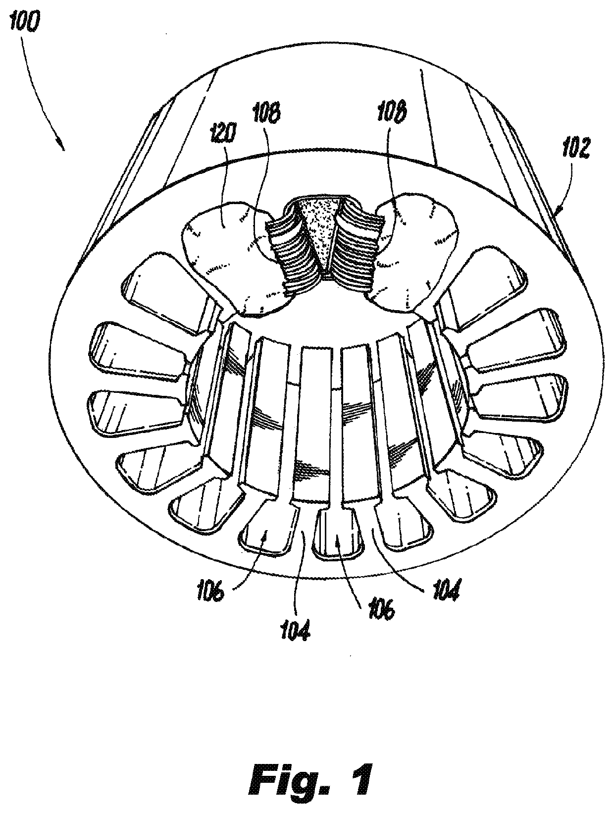
[0015]Reference will now be made to the drawings wherein like reference numerals identify similar structural features or aspects of the subject invention. For purposes of explanation and illustration, and not limitation, a partial view of an exemplary embodiment of an electrical machine in accordance with the invention is shown in FIG. 1 and is designated generally by reference character 100. Other aspects of electrical machine in accordance with the invention, or are provided in FIGS. 2-3b, as will be described. The methods and systems of the invention can be used to improving insulation and sensor reliability.

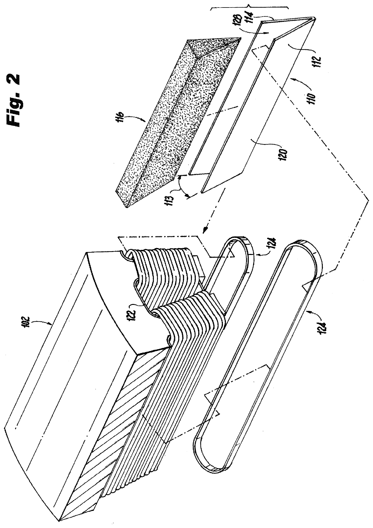
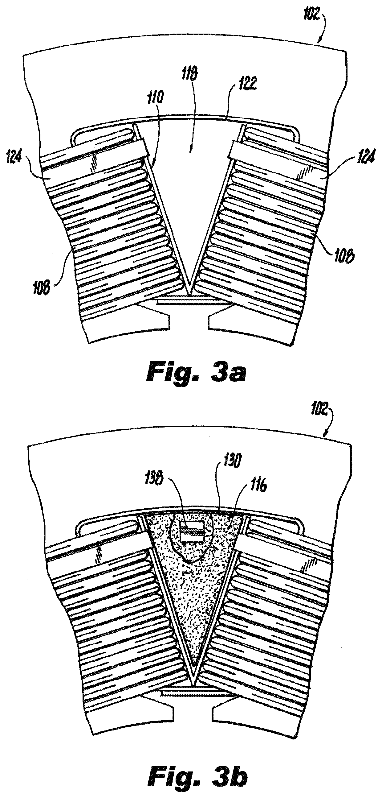
[0016]Referring now to FIGS. 1-3b, an assembly for an electric machine 100 includes a core 102 with a plurality of teeth 104 extending radially outward from the core 102, the plurality of teeth 104 defines a plurality of slots 106 for receiving coils 108. In this instance the electric machine 100 is shown as a stator, but the electric machine 100 can also be a rotor. Each coi...


PUM


Abstract

An assembly for an electric machine including a core with a plurality of teeth extending radially inward from the core, the plurality of teeth defining a plurality of slots for receiving coils, a plurality of coils, each coil wrapping around a respective tooth, a separator in one of the slots including a first leg joined at an angle to a second leg for separating adjacent coils within the slot, an insert between the first leg and the second leg for at least partially filling a space between the first leg and the second leg, and a potting filling space within the slot between the separator, the plurality of coils, and the insert.

Description

BACKGROUNDTechnological Field[0001]The present disclosure relates to coil windings, and more particularly to insulating coil windings.Description of Related Art[0002]A variety of devices are known for insulating motor windings. Motor stators and rotors with concentrated windings that are potted are sometimes subject to eventual cracking of the epoxy material used for potting, especially after thermal cycling. This cracking can lead to eventual damage to the motor windings or thermal sensors that are installed in the stator / rotors slots. This damage makes the motors inoperable and leads to field returns.[0003]The conventional methods and systems have generally been considered satisfactory for their intended purpose. However, there is still a need in the art for insulation having improved reliability and resilience. There also remains a need in the art for such insulation that is economically viable. The present disclosure may provide a solution for at least one of these remaining cha...

Claims


Application Information

Patent Timeline
Patent Type & Authority Applications(United States)
IPC IPC(8): H02K3/32H02K1/14H02K3/18H02K11/25H02K15/10
CPCH02K3/18H02K3/325H02K1/146H02K15/105H02K11/25H02K3/522H02K15/12
Inventor COLDWATE, JOSEPH KENNETHKOENIG, ANDREAS C.
Owner HAMILTON SUNDSTRAND CORP
Why Eureka
Try Eureka