
Friction stir welding tool

a technology of friction stir and welding tool, which is applied in the direction of welding apparatus, metal-working equipment, manufacturing tools, etc., can solve the problems of more easily damaged or broken protrusions, and achieve the effect of more easily damaged

Inactive Publication Date: 2020-10-01
HONDA MOTOR CO LTD
View PDF0 Cites 1 Cited by
  • Summary
  • Abstract
  • Description
  • Claims
  • Application Information

AI Technical Summary

Benefits of technology

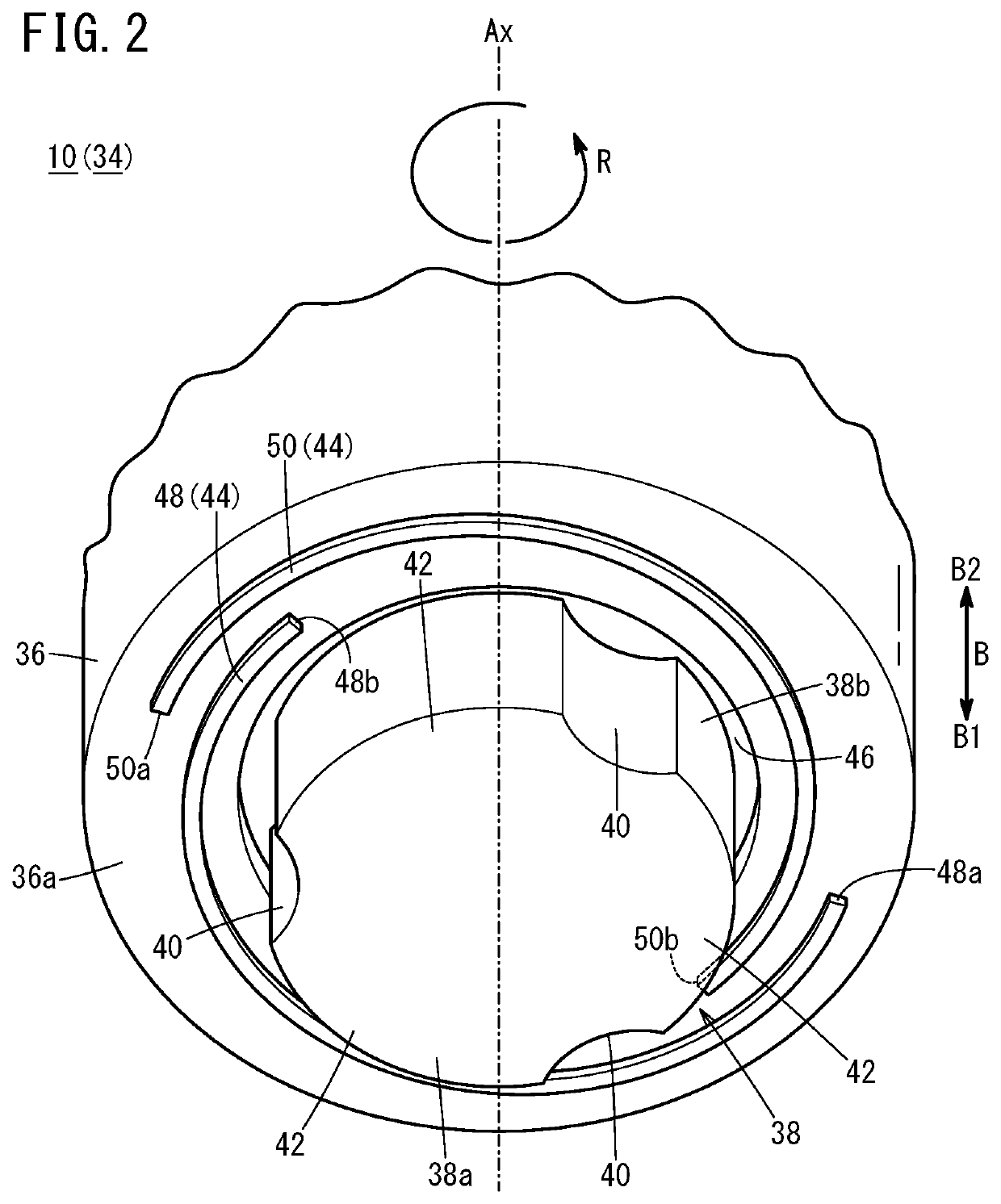
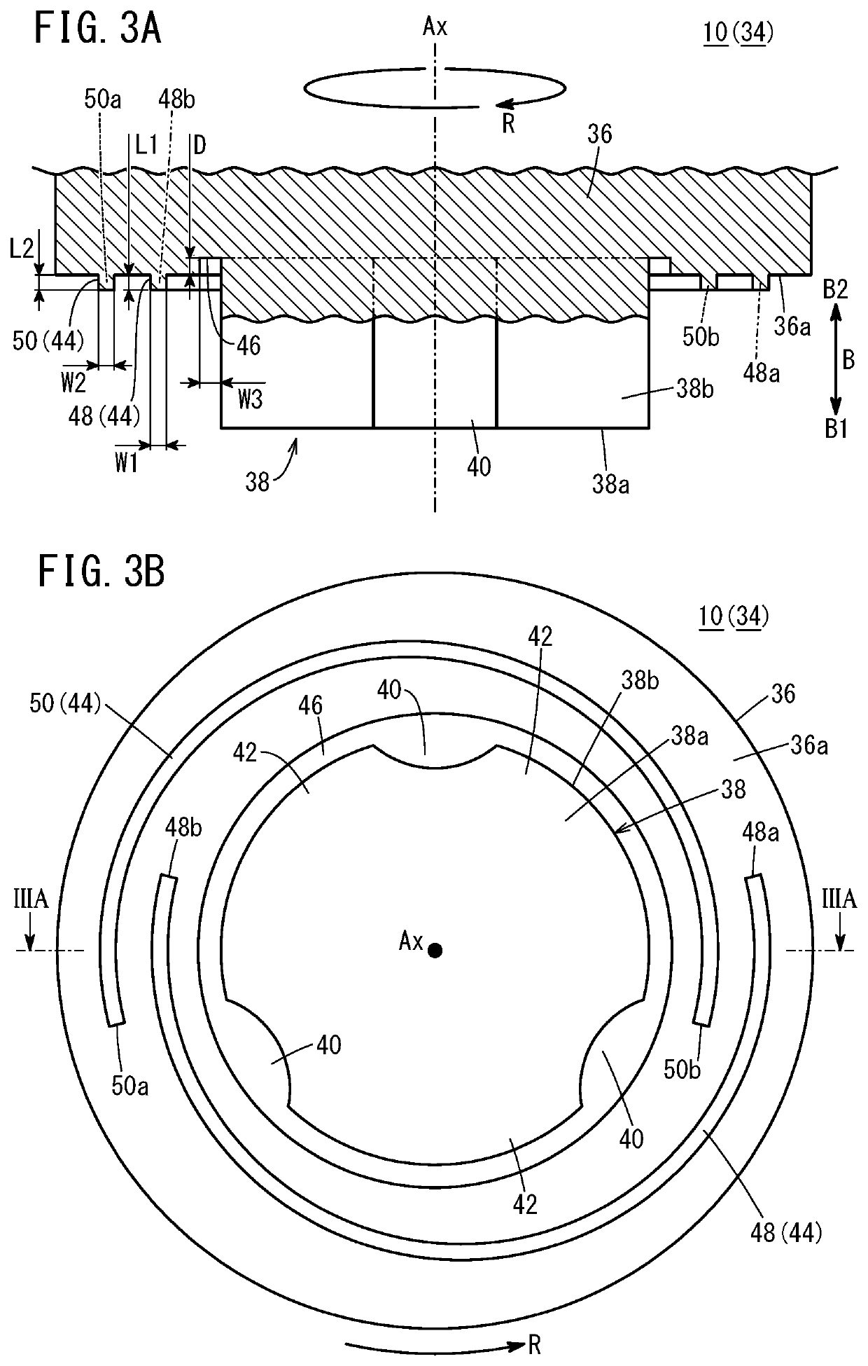
The patent text talks about a problem in friction stir welding where the protrusion on the front of the shoulder of the probe can get damaged easily. The solution proposed is to create a recess between the protrusion and the probe to reduce the chances of damage to the protrusion. This not only allows for efficient guidance of the softened material towards the probe but also increases the amount of material that can be stored between the protrusion and the recess, thus solving the problem of damaged protrusion.

Problems solved by technology

However, as the protruding length of the protrusion increases, the protrusion tends to be broken, or damaged more easily.

Method used


Image

  • Friction stir welding tool
  • Friction stir welding tool
  • Friction stir welding tool

Examples


Embodiment Construction

[0015]Hereinafter, a preferred embodiment of a friction stir welding tool according to the present invention will be described in relation to a friction stir welding system with reference to the accompanying drawings.

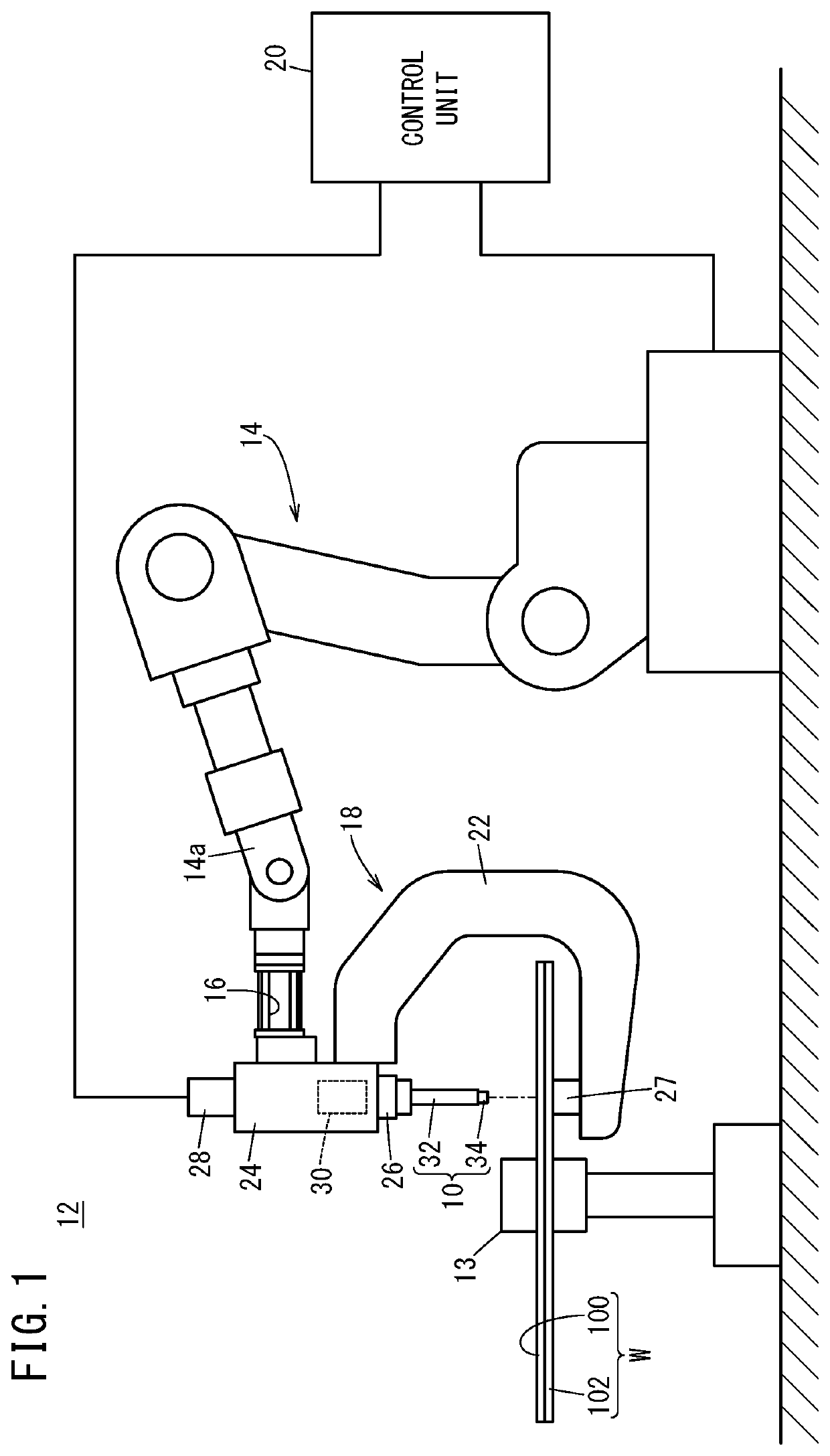
[0016]As shown in FIG. 1, a friction stir welding system 12 is configured to perform friction stir welding (FSW) of a workpiece W by, while rotating a friction stir welding tool 10 (hereinafter also referred to as the “welding tool 10”), pressing the friction stir welding tool 10 against the workpiece W.

[0017]For example, the workpiece W includes a first member 100 in the form of a plate, and a second member 102 in the form of a plate. In the state where the first member 100 and the second member 102 are stacked together, the workpiece W is fixed to a fixing base 13.

[0018]Each of the first member 100 and the second member 102 is made of metal material such as aluminum, magnesium, copper, iron, titanium, or alloy of these materials, etc. The first member 100 and the seco...


PUM

PropertyMeasurementUnit
Timeaaaaaaaaaa

Abstract

A friction stir welding tool includes a shoulder having a flat front end surface perpendicular to a rotation axis, and a probe protruding from the front end surface of the shoulder. The friction stir welding tool is configured to rotate the probe about the rotation axis, and embed the probe inside a workpiece during rotation of the probe to weld the workpiece. Protrusions and a recess are formed in the front end surface of the shoulder. The protrusions are positioned remotely from the probe, and configured to guide first softened material of the workpiece softened at the time of performing friction stir welding to the probe. The recess is positioned between the protrusions and the probe.

Description

CROSS-REFERENCE TO RELATED APPLICATION[0001]This application is based upon and claims the benefit of priority from Japanese Patent Application No. 2019-068816 filed on Mar. 29, 2019, the contents of which are incorporated herein by reference.BACKGROUND OF THE INVENTIONField of the Invention[0002]The present invention relates to a friction stir welding tool which welds a workpiece by rotating a probe about a rotation axis and embedding the probe inside the workpiece during rotation of the probe.Description of the Related Art[0003]Japanese Laid-Open Patent Publication No. 2008-307606 discloses a friction stir welding tool including a shoulder having a flat front end surface perpendicular to a rotation axis and a probe protruding from the front end surface of the shoulder.SUMMARY OF THE INVENTION[0004]However, in the case of providing a protrusion in a front end surface of a shoulder, for guiding softened material of a workpiece which has been softened at the time of performing frictio...

Claims


Application Information

Patent Timeline
IPC IPC(8): B23K20/12
CPCB23K20/1255B23K20/122
Inventor TSUTA, KEISUKESAYAMA, MITSURUMIYAWAKI, AKIYOSHI
Owner HONDA MOTOR CO LTD
Learn More