Connector

a technology of connecting rods and connectors, applied in the direction of coupling device connections, connections effected by permanent deformation, securing/insulating coupling contact members, etc., can solve the problems of side wall breakage, deformation of inner terminals, etc., and achieve the effect of easy deflection, easy deflection, and convenient insertion into the terminal accommodating portion

Inactive Publication Date: 2020-10-01
SUMITOMO WIRING SYST LTD
View PDF0 Cites 0 Cited by
  • Summary
  • Abstract
  • Description
  • Claims
  • Application Information

AI Technical Summary

Benefits of technology

[0008]Thus, the side wall formed with the terminal locking portion is deflected more easily in a direction opposite to a projecting direction of the terminal locking portion as compared to a case where the side wall with the terminal locking portion and the front wall are not divided.
[0009]That is, the side wall is easily deflectable so that the terminal can be inserted easily into the terminal accommodating portion while increasing a locking margin of the terminal locking portion and the terminal. In this way, the terminal will not be damaged during the insertion and is retained securely in the terminal accommodating portion.
[0010]A slit may be formed in the front wall at a boundary to the side wall that has the terminal locking portion. Consideration had been given to forming a slit in the side wall that has the terminal locking portion so that the side wall will deflect more easily. However, a slit in the side wall would reduce the rigidity of the side wall and could cause the side wall to break when being deflected and deformed. On the other hand, a slit in the front wall, as described above, enables the side wall to deflect and deform easily without reducing the rigidity of the side wall.
[0011]The slit may be a mold removal hole formed in front of the terminal locking portion. The mold removal hole may be used to form the terminal locking portion as well as being used to form the slit that divides the front wall and the side wall. In this way, the front wall is not complicated, as compared to the case where the slit is formed in the front wall separately from the mold removal hole. Further, the rigidity of the front wall is not reduced, as compared to the case where both the slit and the mold removal hole are formed in the front wall.
[0012]Accordingly the connector disclosed herein prevents breakage of a terminal and prevents the terminal from easily coming out.

Problems solved by technology

However, the inner terminal then must be pushed forcibly through the upper-stage terminal accommodation opening and the inner terminal may be deformed if the lateral wall is hard to deflect.
However, a slit in the side wall would reduce the rigidity of the side wall and could cause the side wall to break when being deflected and deformed.

Method used


Image

  • Connector
  • Connector
  • Connector

Examples


Embodiment Construction

[0021]A specific example of the connector of the present disclosure is described below with reference to the drawings. Note that the present disclosure is not limited to these illustrations and is intended to be represented by claims and include all changes in the scope of claims and in the meaning and scope of equivalents.

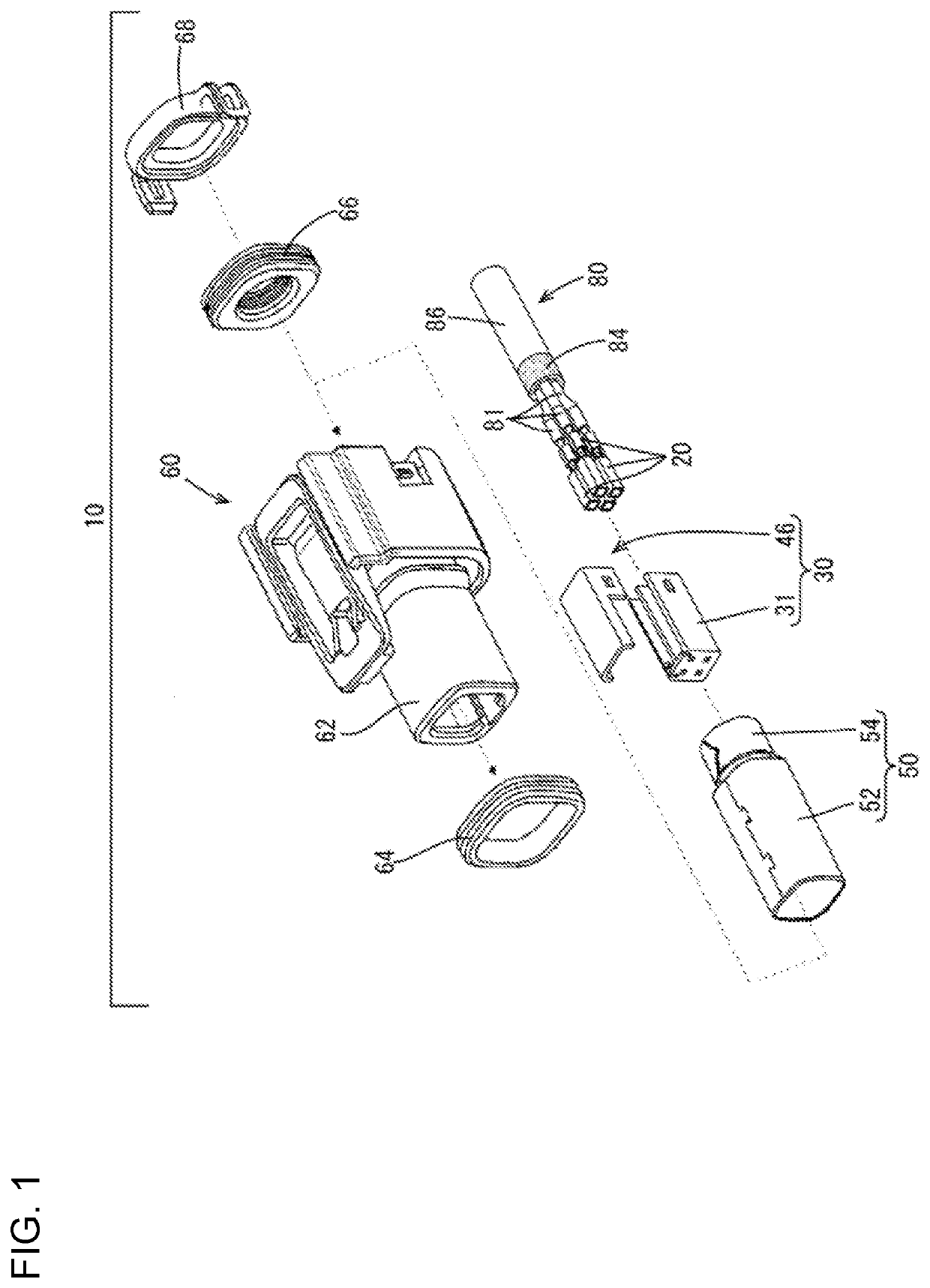
[0022]One embodiment in the present disclosure is described with reference to FIGS. 1 to 6. A connector 10 according to this embodiment is to be mounted on an end part of a shielded cable (an example of a “wire”) 80. As shown in FIG. 1, the connector 10 includes terminals 20 to be connected to an end of the shielded cable 80, an inner housing (an example of a “housing”) 30 for accommodating the terminals 20, an outer conductor 50 for covering the outer periphery of the inner housing30 and an outer housing 60 for accommodating the outer conductor 50.

[0023][Shielded Cable 80]

[0024]As shown in FIG. 1, the shielded cable 80 includes coated wires 81, a braided wire 84 ...


PUM


Abstract

A connector (10) is to be mounted on an end part of a wire, and includes a terminal (20) and a housing. The housing includes a terminal accommodating portion (38). The terminal accommodating portion (38) has two side walls and a front wall (36). The side walls are arranged along the terminal (20), and the front wall (36) is provided between front end parts of the side walls. The terminal accommodating portion (38) includes a terminal accommodation opening (40). The terminal (20) is insertable into the terminal accommodation opening (40) in an intersecting direction intersecting a draw-out direction of the wire. At least one of the side walls includes a terminal locking portion (42) that projects from the side wall. The side wall formed with the terminal locking portion (42) and the front wall (36) are divided.

Description

BACKGROUNDField of the Invention[0001]This disclosure relates to a connector.Related Art[0002]Japanese Unexamined Patent Publication No. 2017-228447 discloses a shield connector with an inner housing for accommodating inner terminals. The inner housing is formed with terminal accommodation chambers including upwardly open upper-stage terminal accommodation chambers. Each terminal accommodation chamber has a terminal holding portion for holding the inner terminal. Each terminal holding portion has a stepped wall that projects laterally from a lateral wall of each terminal accommodation chamber. Each stepped wall is connected to a front wall of the terminal accommodation chamber, and a concave curved recess is formed in a lower part of the stepped wall.[0003]The inner terminal is inserted into the terminal accommodation chamber through the upper-stage terminal accommodation opening and is held in the curved recess by the stepped wall. More particularly, the inner terminal is pushed th...

Claims


Application Information

Patent Timeline
Patent Type & Authority Applications(United States)
IPC IPC(8): H01R13/426H01R13/436
CPCH01R13/426H01R2107/00H01R13/4367H01R4/18H01R13/42H01R13/502H01R13/6592H01R13/422H01R13/506
Inventor KONDO, YUKICHEN, LONG
Owner SUMITOMO WIRING SYST LTD
Why Eureka
Try Eureka