
Detection and monitoring of active optical retroreflectors

a technology of active optical retroreflectors and detection and monitoring, which is applied in the field of imaging systems, can solve the problems of difficult installation of the necessary electronics in the position of adjustable and movable seating, and the inability of outside authorities to completely verify the visual inspection

Active Publication Date: 2020-10-08
JOYSON SAFETY SYST ACQUISITION LLC
View PDF0 Cites 7 Cited by
  • Summary
  • Abstract
  • Description
  • Claims
  • Application Information

AI Technical Summary

Benefits of technology

The patent text describes a system and method for monitoring the interior of a vehicle cabin using images captured by an image sensor. The system includes a light source and an optically active component attached to a reference structure in the vehicle interior. The reference structure is positioned within the field of view of the image sensor. The optically active component is designed to direct reflected light from the reference structure to the image sensor. The reflected light carries information about the status of items in the vehicle interior. The system can also include a light source providing projected light and a 3-D time of flight optical sensor to create a point cloud image of the vehicle interior and the items within it. This allows for a more accurate and detailed monitoring of the vehicle interior.

Problems solved by technology

Visual inspection by outside authorities is not completely reliable given that a vehicle interior is only partially visible from outside of a vehicle.
Seat belt misuse and / or unreliable seat belt monitoring may implicate issues other than simple bodily protection by restraining an occupant during an accident.
Furthermore, many rear seating locations do not currently use seatbelt switches, belt payout sensors, or belt tension sensors.
It may be difficult to install the necessary electronics in adjustable and movable seating locations to support buckle switches, payout or tension sensors as aftermarket control hardware.

Method used


Image

  • Detection and monitoring of active optical retroreflectors
  • Detection and monitoring of active optical retroreflectors
  • Detection and monitoring of active optical retroreflectors

Examples


Embodiment Construction

Overview

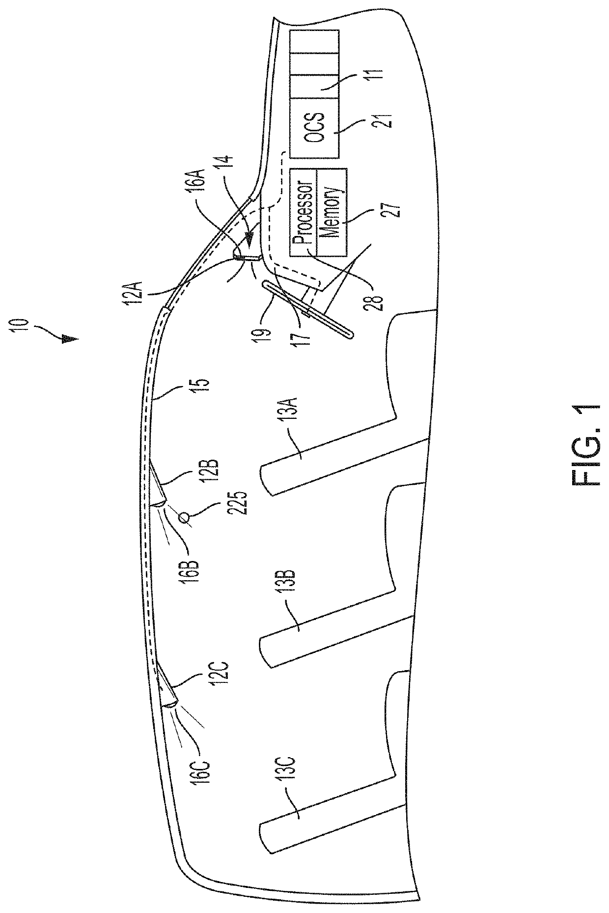
[0049]This disclosure uses electromagnetic sensor(s) such as image sensors, image cameras, and the like to detect and track positions of numerous components of a vehicle interior. In one embodiment, the sensor is an active optical 3-D time of flight imaging system which emits a known waveform (e.g. sinusoidal, pseudo-random, and the like) of electromagnetic wavelength(s) of light which are collocated and / or synchronized with an imager detector array where the amplitude of the detected signal is proportional to the reflected light at the light wavelength(s). Such a sensor can collect both the reflected light intensity of surfaces in the field of view of the imager and the distance of the surface from the imager detector.

[0050]The light is emitted and hits the surface of all objects within a line of sight. As a function of the geometric arrangement and compositional materials of the object, a portion of the light is reflected back toward an imager detector array. Signal proces...


PUM


Abstract

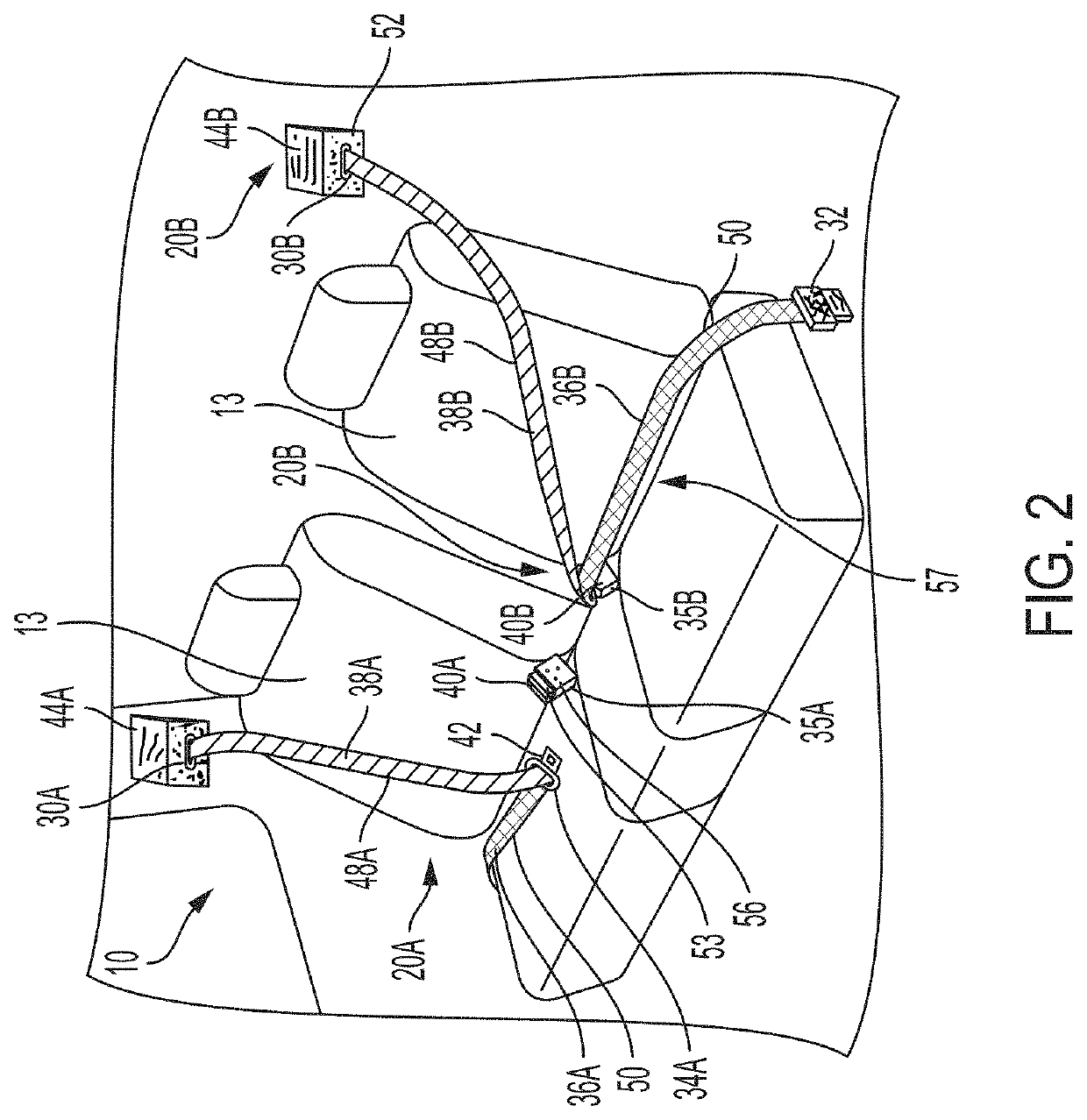
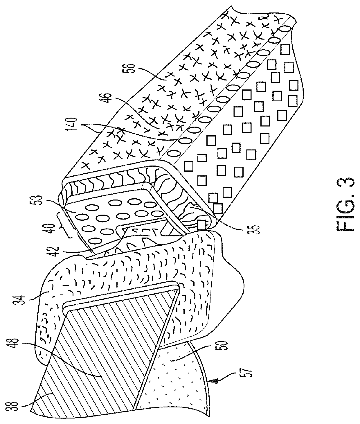
A system of detecting vehicle components in operation in a vehicle includes at least one light source configured to emit a predetermined wavelength of light onto structures within the vehicle, wherein at least one of the structures may include a passenger seat belt assembly having a pattern of reflection and retroreflective surfaces tuned to a predetermined wavelength at a preferred luminance. At least one 3-D time of flight camera is positioned in the vehicle to receive reflected light from the structures in the vehicle and provide images of the structures that distinguish the preferred luminance of the pattern from other structures in the vehicle. A computer processor connected to computer memory and the camera includes computer readable instructions causing the processor to reconstruct 3-D information in regard to respective images of the structures and calculate a depth measurement of the distance of the reflective pattern on the passenger seat belt assembly from the camera.

Description

CROSS REFERENCE TO RELATED APPLICATIONS[0001]This application claims priority to and incorporates entirely by reference U.S. Provisional Patent Application Serial No. 62 / 829,475 filed on Apr. 4, 2019, and entitled “Detection and Monitoring of Active Optical Retroreflectors.”TECHNICAL FIELD[0002]The disclosure presented herein relates to imaging systems within a vehicle passenger cabin and is directed to locating, identifying, and highlighting changes in status of occupants and structures in the vehicle cabin.BACKGROUND[0003]Seat belts are standard equipment for almost every kind of vehicle in which occupants are transported in today's transportation systems. Not only are original equipment manufacturers (OEMs) required to meet strict standards for seat belt engineering and installation, but in many scenarios, vehicle occupants are required to wear seat belts as a matter of law. Even with manufacturing regulations and use laws in place, however, overall vehicle safety is entirely dep...

Claims


Application Information

Patent Timeline
IPC IPC(8): G06K9/00B60Q3/20B60Q3/70G06K9/20G06T7/50G06T7/70G06T7/20
CPCG06T7/70B60Q3/70G06K9/2027B60Q3/20G06K9/2036G06T7/50G06K9/00832G06T2207/10028G06T7/20G06T2207/30268G06T2207/10048G06V20/59B60Q3/242
Inventor RAMAGLIA, JOSHUACECH, LEN
Owner JOYSON SAFETY SYST ACQUISITION LLC
Learn More