Suture needle

a needle and suture technology, applied in the field of suture needles, can solve the problems of erroneously grasping the tip section, the tip section may be subjected to a load, etc., and achieve the effect of low distinguishability as a mark

Pending Publication Date: 2020-10-15
SMR CO LTD
View PDF5 Cites 1 Cited by
  • Summary
  • Abstract
  • Description
  • Claims
  • Application Information

AI Technical Summary

Benefits of technology

[0004]However, when the suture needle is grasped at the tip section, and then pulled out, the tip section may be subjected to a load. To avoid this, it is necessary to pull out the suture needle, not by grasping the tip section with the needle holder, but by grasping a further base end side (a side where a suture thread is threaded through) with respect to the tip section. Forming the third lines on the suture needle as in Patent Literature 1 and using this as a mark ensure avoiding the tip section from being grasped, but there still remains a problem of erroneously grasping the tip section since its distinctiveness as a mark is not high.

Problems solved by technology

However, when the suture needle is grasped at the tip section, and then pulled out, the tip section may be subjected to a load.
Forming the third lines on the suture needle as in Patent Literature 1 and using this as a mark ensure avoiding the tip section from being grasped, but there still remains a problem of erroneously grasping the tip section since its distinctiveness as a mark is not high.

Method used


Image

  • Suture needle
  • Suture needle
  • Suture needle

Examples


first embodiment

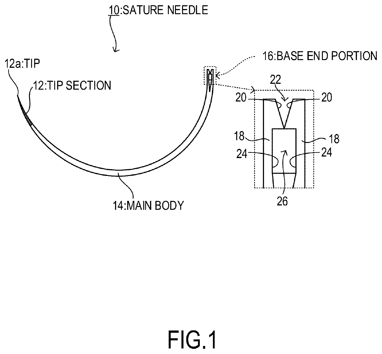
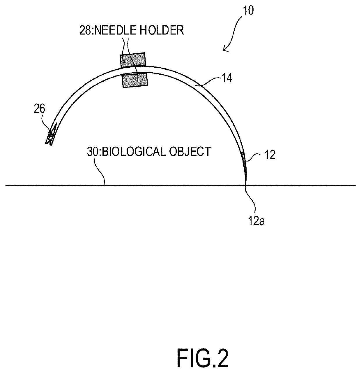
[0017]FIG. 1 illustrates a schematic diagram of a suture needle of a first embodiment and a partially enlarged view thereof. A surgical suture needle 10 of this embodiment uses, for example, stainless steel as a material, and has an outer shape curved into an approximately semicircle. The suture needle 10 is configured of a tip section 12, a main body 14, and a base end portion 16. Cross-sectional shapes of the tip section 12, the main body 14, and the base end portion 16 are not particularly limited, and, for example, a circular shape and a polygon shape, such as a triangular shape, are applicable. This cross-sectional shape can be designed to change as moving in a longitudinal direction of the suture needle 10. It should be noted that the suture needle 10 has a portion up to approximately ⅓ of the length of the suture needle 10 including the tip section 12, and the portion serves as an edge that pierces into a biological object 30 (see FIG. 2).

[0018]The tip section 12 is a portion...

second embodiment

[0034]FIG. 8 is a partially enlarged view of the suture needle in a second embodiment. As illustrated in FIG. 8, a suture needle 10A according to the second embodiment has an outer shape in common with the suture needle 10 of the first embodiment. The tip section 12 has a tip region 12b from the tip 12a of the suture needle 10A to a midpoint in the longitudinal direction of the tip section 12. The tip region 12b is colored in a color different from a color of a portion other than that (tip region 12b) of the tip section 12. In particular, the tip region 12b is preferred to be colored in black, or may be colored in white, gold, and silver, other than black.

[0035]Thus, coloring the tip region 12b in a color different from a color of another portion of the tip section 12 causes the doctor to visually recognize a presence of the tip 12a that exposes again from the biological object 30 after piercing the suture needle 10 into the biological object 30 (not illustrated in FIG. 8), thereby ...

third embodiment

[0036]FIG. 9 is a partially enlarged view of a suture needle of a third embodiment. As illustrated in FIG. 9, a suture needle 10B of the third embodiment has an outer shape in common with the suture needle 10 of the first embodiment. The tip region 12b from the tip 12a of the suture needle 10 to the midpoint in the longitudinal direction of the tip section 12 in the tip section 12 is not colored. The tip region 12b is in a state where a surface of the suture needle 10 is exposed and is a portion where a color (for example, silver or brown) of a material of the suture needle 10 appears.

[0037]Thus, not coloring the tip region 12b causes the doctor to visually recognize a presence of the tip 12a exposed again from the biological object 30 after piercing the suture needle 10 into the biological object 30 (not illustrated in FIG. 9), thereby ensuring the enhanced operation efficiency of suturing.

[0038]In the second embodiment and the third embodiment, a ratio of the length of the tip reg...


PUM


Abstract

The surgical suture needle includes a tip section, a main body, and a base end portion. The tip section is colored in a color different from a color of other portions. The tip section has a tapered shape, and a length of the tip section is 10% of a whole length of the suture needle. When the suture needle penetrating the biological object is pulled out by grasping with a needle holder, grasping the tip section of the suture needle easily breaks the suture needle. Therefore, a doctor grasps a portion other than the tip section with the needle holder. The colored tip section ensures the doctor easily distinguishing the tip section from the other portions. Coloring the tip section in red, green, purple, or pink ensures avoiding erroneously grasping the tip section since the tip section is unnoticeable at a suture position where blood is attached.

Description

TECHNICAL FIELD[0001]The present invention relates to a suture needle.BACKGROUND ART[0002]JP2015-58112A discloses a suture needle for the purpose of facilitating distinguishing a front and a back, and a direction of a suture needle. In the suture needle, a first line and a second line are formed on an outer peripheral side and an inner peripheral side, respectively, of the suture needle whose entire shape is curved, along a longitudinal direction of the suture needle. Furthermore, a third line that surrounds a circumferential direction of the suture needle is formed. A plurality of the third lines are formed at constant intervals along the longitudinal direction of the suture needle.[0003]When a suture needle is used, the following operation is typically performed: the suture needle is grasped with a needle holder, for example, a tip of the suture needle is pierced from a skin of a patient (a biological object) toward a subcutaneous tissue (a biological object), the suture needle is...

Claims


Application Information

Patent Timeline
Patent Type & Authority Applications(United States)
IPC IPC(8): A61B17/06A61B17/062A61B90/92
CPCA61B17/062A61B2017/0608A61B90/92A61B2090/0807A61B17/06004A61B17/06109A61B2017/06019A61B17/06066
Inventor MATSUMOTO, KEISUKE
Owner SMR CO LTD
Why Eureka
Try Eureka