
System for wireless power charging

a wireless power charging and wireless charging technology, applied in the direction of transmission, electric vehicles, electrical equipment, etc., can solve the problems of increasing the cost of the system, and reducing the service life of the system

Active Publication Date: 2020-10-15
POWERMAT TECHNOLOGIES
View PDF0 Cites 7 Cited by
  • Summary
  • Abstract
  • Description
  • Claims
  • Application Information

AI Technical Summary

Benefits of technology

This patent describes a way to calibrate a system that uses a relay and a transmitter to transfer power to a device. The method involves determining the best settings for the relay and transmitter based on the characteristics of the device being charged, such as the frequency and amplitude of power needed. By measuring the operation of the transmitter and calculating the performance of the relay, the system can be optimized for efficient power transfer. This can be useful for charging devices like phones or other devices that need a fast and reliable charging solution.

Problems solved by technology

Commercially available systems are limited to a maximum distance of approx.
Typically, the systems are installed on top of surfaces, such as tables, bars, or the like that are accessible to users, thus require decorative appearance and hazards free installation.
In some cases, the transmitter of such commercially available systems can be installed inside the cutout hole in the surface, which complicate the installation and raise its cost, on top of damaging the customer's furniture.
Clearly, such commercially available solutions are not desired in the consumers marketplace.
Moreover, the wireless power charging level of these available solutions is limited for charging handheld devices requiring less than 15 watts.

Method used


Image

  • System for wireless power charging
  • System for wireless power charging
  • System for wireless power charging

Examples


Embodiment Construction

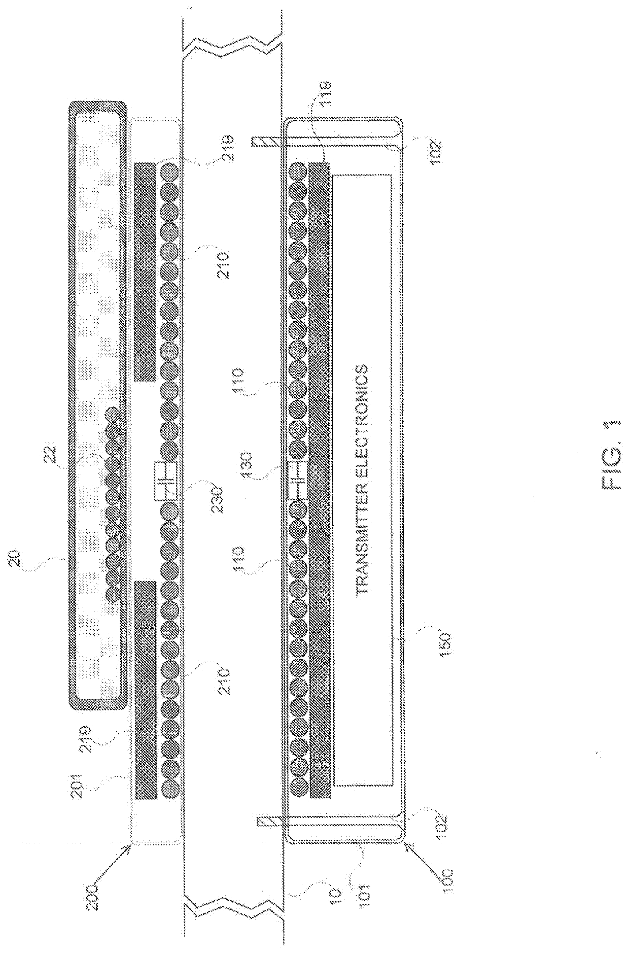
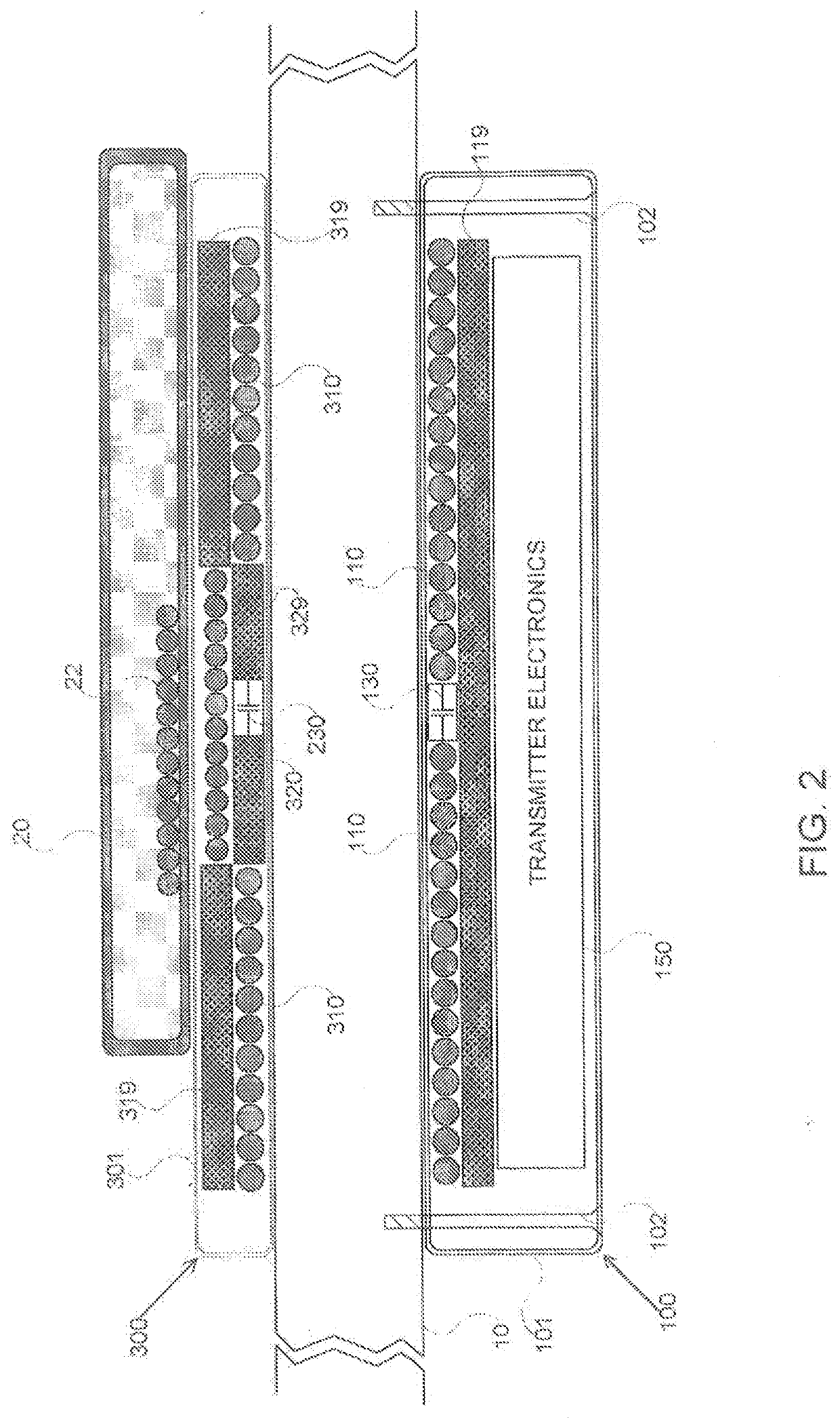
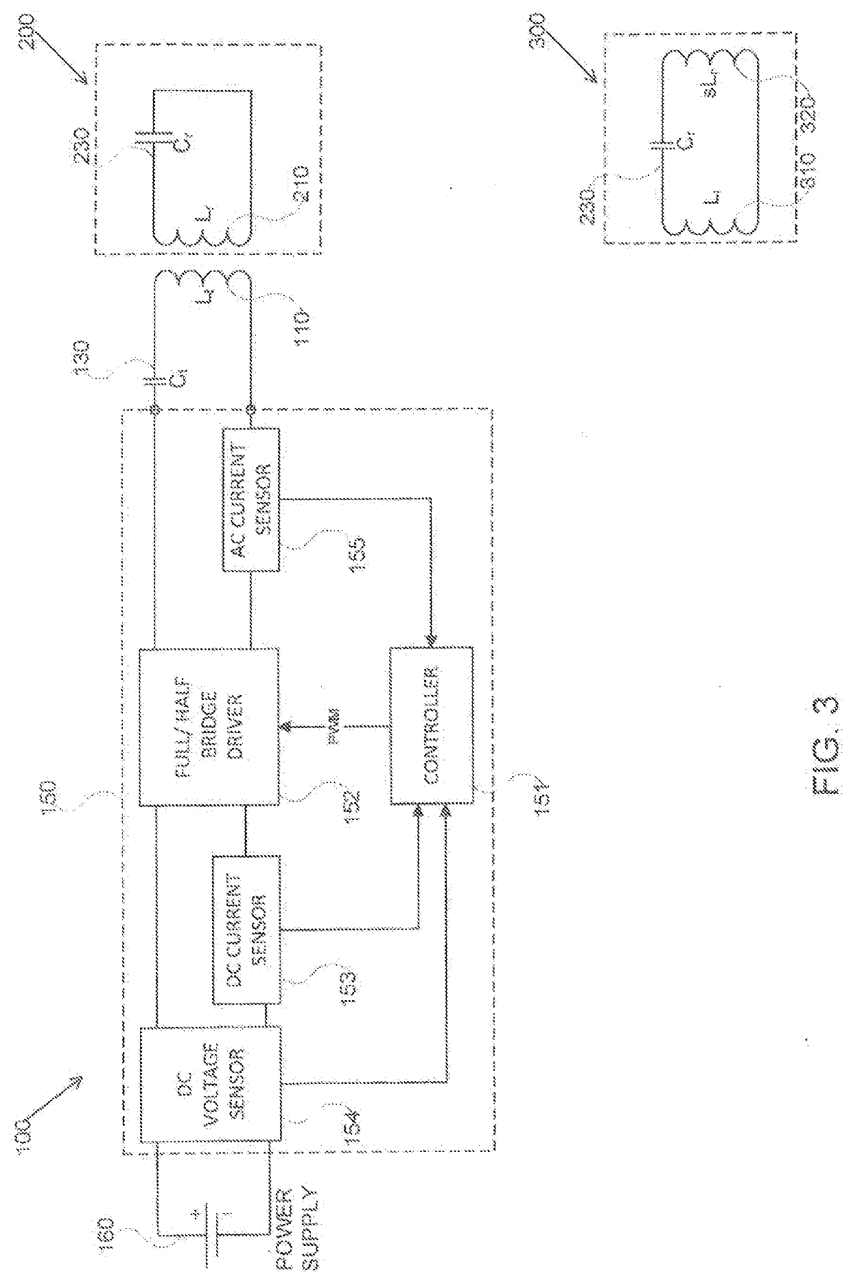
[0020]Before explaining at least one embodiment of the disclosed subject matter in detail, it is to be understood that the disclosed subject matter is not limited in its application to the details of construction and the arrangement of the components set forth in the following description or illustrated in the drawings. The disclosed subject matter is capable of other embodiments or of being practiced or carried out in various ways. Also, it is to be understood that the phraseology and terminology employed herein is for the purpose of description and should not be regarded as limiting. The drawings are generally not to scale. For clarity, non-essential elements were omitted from some of the drawings.

[0021]The terms “comprises”, “comprising”, “includes”, “including”, and “having” together with their conjugates mean “including but not limited to”. The term “consisting of” has the same meaning as “including and limited to”.

[0022]The term “consisting essentially of” means that the compo...


PUM


Abstract

According to a first aspect of the present disclosed subject matter, a dynamic calibration method in a system comprising a relay, having a coil, adapted to inductively transfer power for charging a device and a transmitter, having a coil and a controller configured to inductively transmit to the relay the power for charging the device, wherein the transmitter and the relay are separated by a medium, the method comprising: determining operating parameters selected from a group consisting of minimal and maximal operating frequency; direction of power increase relative to operating frequency; minimal and maximal duty cycle; minimal and maximal operating amplitude; and any combination thereof; wherein the operating parameters and a ping frequency are determined based on dynamic measurements of the transmitter operation and calculations executed by the controller during the calibration.

Description

TECHNICAL FIELD[0001]The present disclosed subject matter relates to wireless power charging systems. More particularly, the present disclosed subject matter relates to induction charging through medium and methods for self-calibration.CROSS-REFERENCE TO RELATED APPLICATION[0002]This application claims priority under 35 U.S.C. § 119(e) from the following co-pending provisional patent applications, which are all incorporated by reference for all purposes.[0003]a. U.S. Provisional Patent Application No. 62 / 467,903, by Itay Sherman, Elieser Mach, Ilya Gluzman, Amir Salhuv, titled “Large Range Inductive Tx”, filed on Mar. 7, 2017.[0004]b. U.S. Provisional Patent Application No. 62 / 535,987, by Itay Sherman, Elieser Mach, Sharon Ben-Itzhak, Amir Salhuv, titled “Smart Inductive extensions”, filed on Jul. 24, 2017.[0005]c. U.S. Provisional Patent Application No. 62 / 584,919, by Itay Sherman, Elieser Mach, Amir Salhuv and Aya Kantor, titled “Under the table inductive Tx additional topics-exte...

Claims


Application Information

Patent Timeline
IPC IPC(8): H02J50/12H02J7/02H02J50/80H02J50/50
CPCH02J50/50H02J50/80H02J50/12H02J7/02H04B5/79H04B5/24
Inventor SHERMAN, ITAYGLUZMAN, ILYAMACH, ELIESERSALHUV, AMIRBEN-ITZHAK, SHARONKANTOR, AYA
Owner POWERMAT TECHNOLOGIES
Learn More