Method of illuminating a light valve with an overdrive level

Inactive Publication Date: 2006-02-23
HEWLETT PACKARD DEV CO LP
View PDF2 Cites 7 Cited by
  • Summary
  • Abstract
  • Description
  • Claims
  • Application Information

AI Technical Summary

Benefits of technology

[0014] A method of illuminating a light valve using a light source having a nominal power dissipation level is provided. The light valve includes a light input, a light output, a spatial light modulator having an array of pixels, a color sequencer for sequentially selecting one of a first, a second, and a third colorband of light. In the method, power is supplied to the light source to generate light and illuminate the spatial light modulator through the light input. During an initial portion of an illuminatio

Problems solved by technology

However, they are typically too slow to use pulse width modulation to achieve gray levels.
Ferroelectric liquid crystal-based spatial light modulators suffer the disadvantage that, after each time the drive signal has been applied to a pixel electrode to cause the pixel to modulate the light either transmitted/reflected by it, the DC balance of the pixel must be restored.
However, modulating the light source as just described reduces the light throughput of the light valve to about half of that which could be achieved if DC balance restoration were unnecessary.
This mea

Method used


Image

  • Method of illuminating a light valve with an overdrive level
  • Method of illuminating a light valve with an overdrive level
  • Method of illuminating a light valve with an overdrive level

Examples


Embodiment Construction

[0042] For simplicity and illustrative purposes, the present invention is described by referring mainly to an exemplary embodiment thereof. In the following description, numerous specific details are set forth in order to provide a thorough understanding of the present invention. It will be apparent however, to one of ordinary skill in the art, that the present invention may be practiced without limitation to these specific details. In other instances, well known methods and structures have not been described in detail so as not to unnecessarily obscure the present invention.

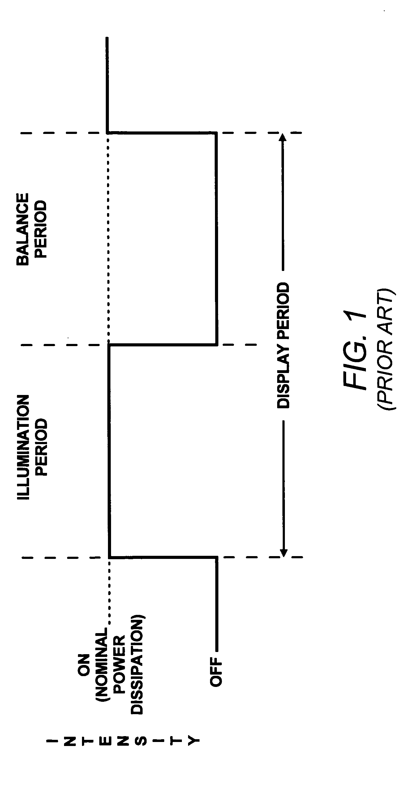
[0043] The invention is based, in part, on the concept that a light source can be made to operate at an intensity in excess of its nominal power dissipation level in a controlled manner to generally cause the light output of the light source to relatively quickly reach a nominal light output level. That is, the modulation power, voltage or current, may be supplied to the light source in a manner to generally ca...


PUM


Abstract

A method of illuminating a light valve using a light source having a nominal power dissipation level. In the method, power is supplied to the light source to generate light and illuminate the spatial light modulator through the light input. During an initial portion of an illumination period of each colorband period, the power supplied to the light source is increased to an overdrive level above a nominal power dissipation level. In addition, the power supplied to the light source is decreased following the initial portion of each colorband period in the illumination period to thereby increase the intensity of the light source during the initial portions of the illumination periods of each colorband period and maintain a substantially uniform light output throughout the colorband periods.

Description

BACKGROUND OF THE INVENTION [0001] A need exists for various types of video and graphics display devices with improved performance and lower cost. For example, a need exists for miniature video and graphics display devices that are small enough to be integrated into a helmet or a pair of glasses so that they can be worn by the user. Such wearable display devices would replace or supplement the conventional displays of computers and other devices. A need also exists for a replacement for the conventional cathode-ray tube used in many display devices including computer monitors, conventional and high-definition television receivers and large-screen displays. Both of these needs can be satisfied by display devices that incorporate a light valve that uses as its light control element a spatial light modulator. Spatial light modulators are typically based on liquid crystal material, but may also be based on arrays of moveable mirrors. [0002] Liquid crystal-based spatial light modulators ...

Claims


Application Information

Patent Timeline
IPC IPC(8): G09G5/00
CPCH04N9/3111H04N9/3197H04N9/315H04N9/3114
Inventor KUO, HUEI PEIKURAMOTO, AKINOBU
Owner HEWLETT PACKARD DEV CO LP
Why Eureka
Try Eureka