Multi-use ball tee

a multi-use, ball tee technology, applied in the field of sports/fitness/recreation equipment, can solve the problems of reducing the chance of ball tee damage, and achieve the effect of greater stability, greater stabilization of ball tee, and greater stability

Active Publication Date: 2020-10-22
JOHNSON DAVID
View PDF0 Cites 0 Cited by
  • Summary
  • Abstract
  • Description
  • Claims
  • Application Information

AI Technical Summary

Benefits of technology

[0007]A first embodiment of the invention may provide a tee for supporting a ball. The ball tee includes a column and two platforms. The column is generally cylindrical, hollow, and with an aperture at each end, allowing a continuous unobstructed view through one end to and through the other end. Said column is identical on top and bottom and dimensioned, at the bottom, to receive the narrow end of one platform, and, at the top, to receive the narrow end of another platform, communicating the column with a platform at the top of said column and a platform at the bottom of said column, or either a platform at the top of said column with no platform at the bottom, or a platform at the bottom of said column with no platform at the top, providing a plurality of difficulty levels when utilizing said tee. Said column is configured to stand upright, on a multitude of natural and manufactured surfaces, without a platform attached to the bottom, and to support a ball when a platform is not attached to the top. Said column is narrower than the wide end of each platform and is less stable on said surfaces than when a platform is attached to bottom of said column, and provides less support for a ball than when a platform is attached to top of said column. A platform is disposed at the bottom of the ball tee, below the column, and configured to fit partially within said column. Said platform is hollow with an aperture at each end, allowing a continuous unobstructed view through one end to and through the other end. Said platform presents a generally funnel-like shape, of which the narrow end of the funnel shape is extended and flattened, and is configured to fit within said column, communicating the platform with the column. The wide end of said platform is wider than the column, faces downward and interfaces with a multitude of natural and manufactured surfaces, providing greater stability to the ball tee than when platform is not attached. A platform may be disposed atop the ball tee, above the column, and configured to fit partially within said column. Said platform is hollow with an aperture at each end, allowing a continuous unobstructed view through one end to and through the other end. Said platform presents a generally funnel-like shape, of which the narrow end of the funnel shape is extended and flattened, and is configured to fit within said column, communicating the platform with the column. The wide end of said platform is wider than the column and is oriented upward to support a ball, providing greater stability for a ball than when platform is not attached to the column. The ball tee, at any level of assembly, has an aperture at the top and bottom, allowing a continuous unobstructed view through one end to and through the other end.
[0009]Another embodiment of the invention may provide a platform at the bottom of the ball tee for greater stabilization of the ball tee, wherein the ball tee is configured to support a ball. Said platform is disposed at the bottom of said tee, below the column, when ball tee is erected in an upright position, and configured to fit partially within said column. Said platform is hollow with an aperture at each end, allowing a continuous unobstructed view through one end to and through the other end. Said platform presents a generally funnel-like shape, of which the narrow end of the funnel shape is extended and flattened, and is configured to fit within said column, communicating the platform with the column. The wide end of said platform is wider than said column. The wide end of said platform is oriented downward and interfaces with a multitude of natural and manufactured surfaces, providing greater stability to the ball tee than when said platform is not attached.
[0010]Another embodiment of the invention may provide a platform at the top of the ball tee for greater stabilization of a ball, wherein the ball tee is configured to support a ball. The platform is disposed atop said tee, above the column, when tee is erected in an upright position, and configured to fit partially within said column. Said platform is hollow with an aperture at each end, allowing a continuous unobstructed view through one end to and through the other end. Said platform presents a generally funnel-like shape, of which the narrow end of the funnel shape is extended and flattened, and is configured to fit within said column, communicating the platform with the column. The wide end of said platform is wider than the column. The wide end of said platform is oriented upward to support a ball, providing greater stability for a ball than when platform is not attached to the column.

Problems solved by technology

When using the ball tee, there is no objective to strike at said tee or a ball resting upon said tee, or subject it to any significant impact, thus greatly reducing the opportunity for the ball tee to sustain damage, particularly catastrophic damage.

Method used


Image

  • Multi-use ball tee
  • Multi-use ball tee
  • Multi-use ball tee

Examples


Embodiment Construction

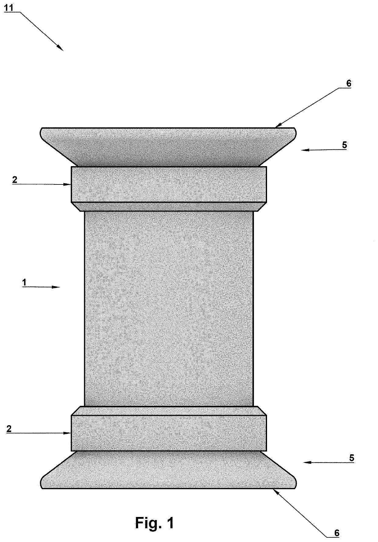
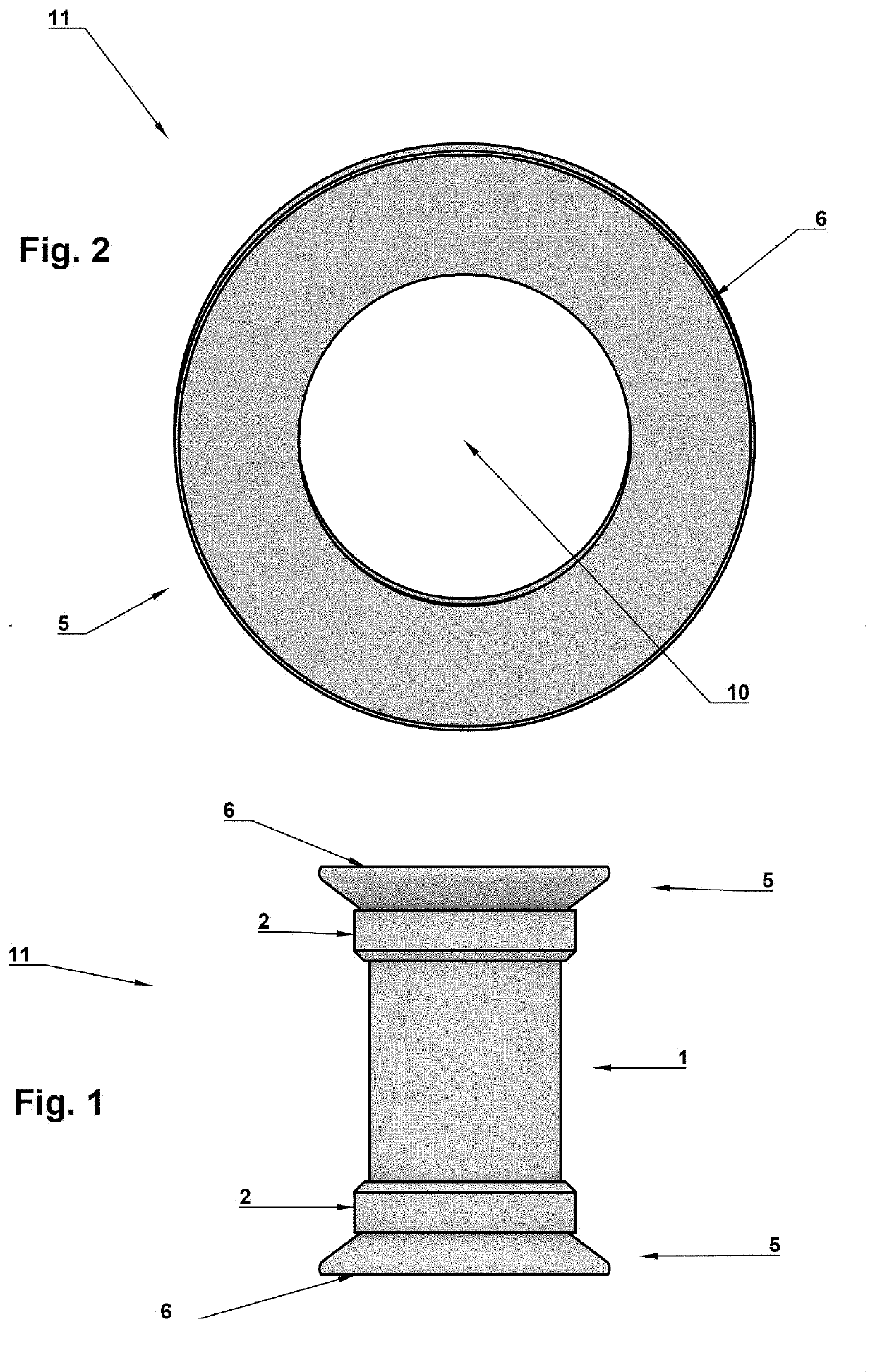
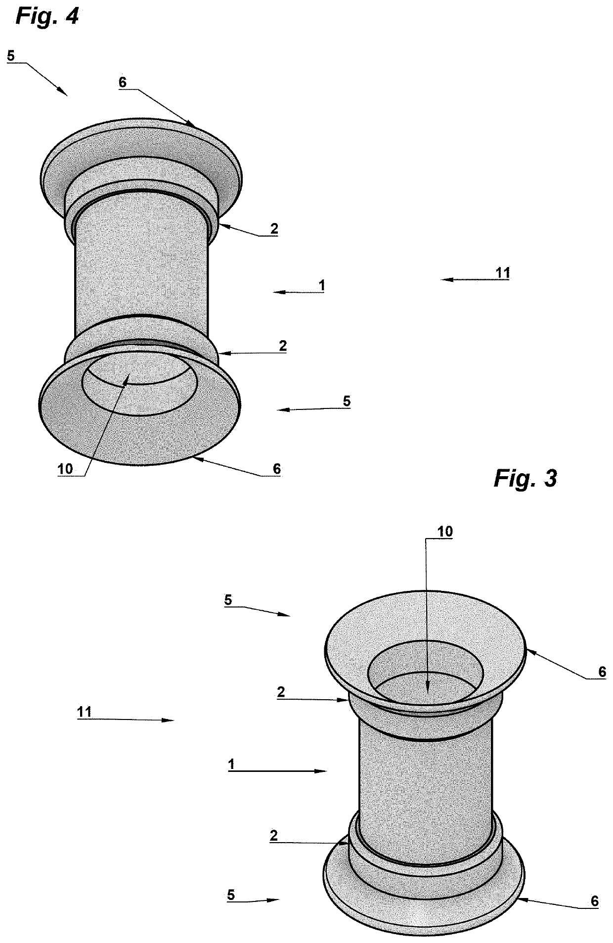
[0033]It should be understood that the Figures are merely schematic and are not drawn to scale. It should also be understood that the same reference numerals are used throughout the Figures to indicate the same parts.

[0034]As best depicted in FIG. 1, a ball tee 11 of embodiments of the invention comprises a column 1, and two platforms 5, one platform 5 serving as a ball holder, the other platform 5 serving as a base. The platforms 5 are inserted into the narrow end receiving docks 2 on either end of the column 1. The platform 5 sitting atop the ball tee 11 serves as a ball holder, the platform 5 at the bottom of the ball tee 11 serves as the base. The bottom platform 5 interfaces with a multitude of natural and manufactured surfaces. One platform 5, top or bottom, or both platforms 5 may be removed to decrease stability of the ball tee, thus increasing difficulty of use, to make utilizing the ball tee more challenging.

[0035]To benefit the reader, a discussion of the field of use of ...


PUM


Abstract

This invention is directed to a ball tee for supporting a ball. A ball tee comprises a column, and two platforms. The column is hollow and is generally identical on top and bottom, and dimensioned, at the bottom, to receive the narrow end of one platform, and, at the top, to receive the narrow end of another platform, communicating the column to both platforms, or one platform on the bottom with no platform communicated to the top, or either one platform on the top with no platform communicated to the bottom, providing a plurality of configurations and difficulty levels when utilizing the ball tee. The column is configured to stand upright on a multitude of natural and manufactured surfaces, with no platform communicated to the bottom, and to support a ball when there is no platform communicated to the top.

Description

CROSS-REFERENCE TO RELATED APPLICATIONS[0001]This non-provisional patent application is a continuation and claims priority benefit with regard to all common subject matter of earlier filed U.S. Provisional Patent Application No. 62 / 836,715, filed Apr. 21, 2019, and entitled ‘Sports, fitness, and academic training system.’BACKGROUND OF THE INVENTION1. Field of Endeavor[0002]Embodiments of the invention relate to sports / fitness / recreation equipment, and equipment related to physical and cognitive abilities, including the assessment of, improvement of, and rehabilitation / therapy of said abilities. More specifically, embodiments of the invention relate to a dual-sided, multi-arrangeable, multi-use ball tee from which users may pick up a ball; on which users may set down a ball; on which users may exchange a ball.2. Prior Art[0003]Athletes and fitness participants often rely on equipment to assess or enhance performance, or as necessary components of certain sports or activities. Tees ar...

Claims


Application Information

Patent Timeline
Patent Type & Authority Applications(United States)
IPC IPC(8): A63B69/00
CPCA63B69/0075A63B71/03A63B2209/00A63B2225/09A63B2225/605A63B2071/0694A63B2225/093A63B2214/00
Inventor JOHNSON, DAVID
Owner JOHNSON DAVID
Why Eureka
Try Eureka