Liquid transfer device and method of use
- Summary
- Abstract
- Description
- Claims
- Application Information
AI Technical Summary
Benefits of technology
Problems solved by technology
Method used
Image
Examples
Embodiment Construction
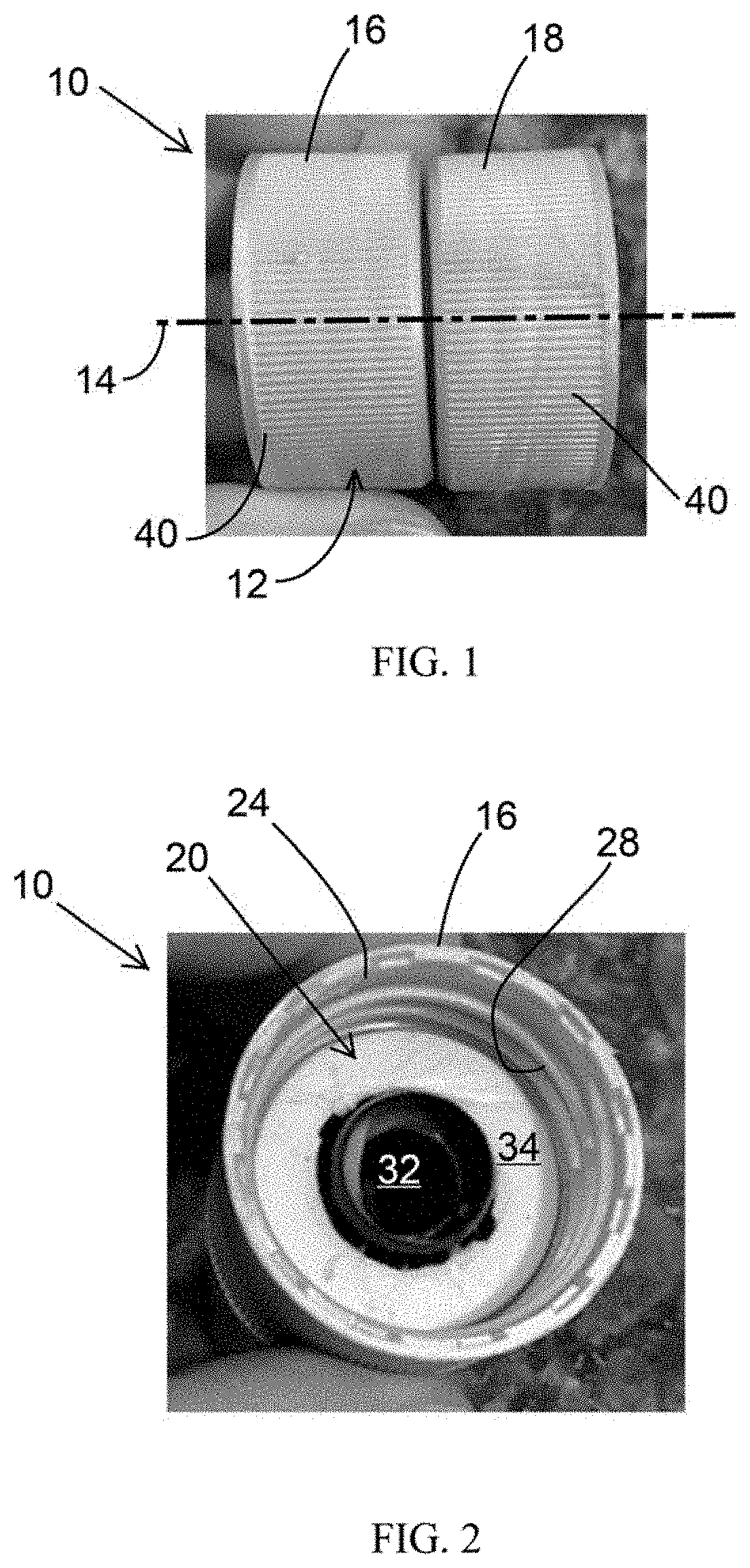
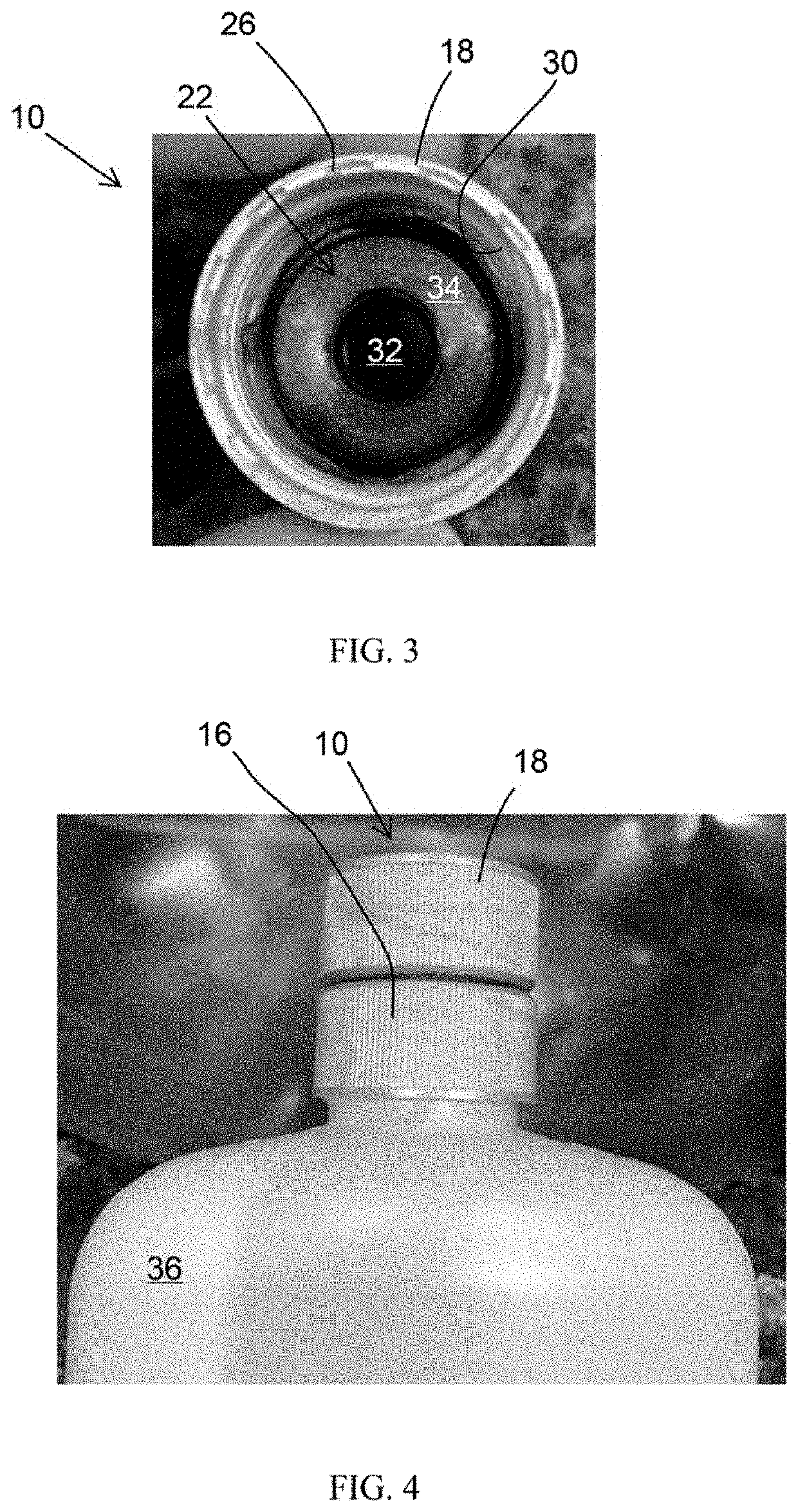
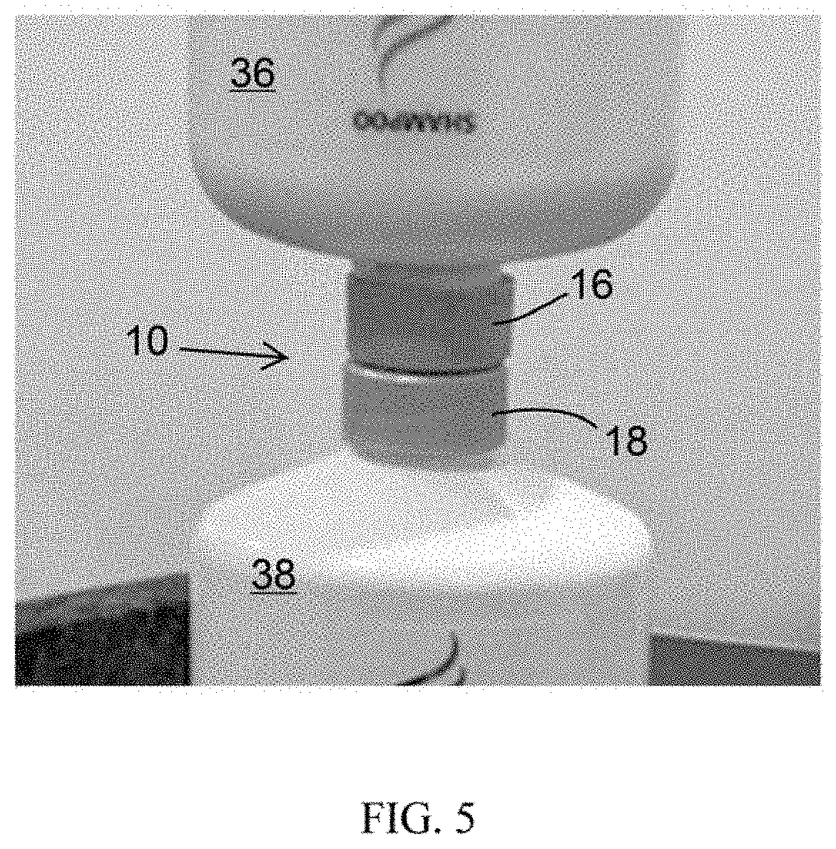
[0013]FIGS. 1 through 3 schematically represent a nonlimiting embodiment of a liquid transfer device 10. The device 10 includes a generally cylindrical body 12 that defines an axis 14 of the device 10. The body 12 comprises first and second cap members 16 and 18 that are disposed at opposite axial ends of the body 12. As seen in FIGS. 2 and 3, each cap member 16 and 18 defines an interior cavity 20 and 22, respectively, each defining an axial opening 24 and 26 at a respective axial end of the body 12. The cavities 20 and 22 are coaxially aligned along the axis 14 of the body 12 and define interior walls within the cap members 16 and 18 on which female threads 28 and 30, respectively, are formed. The female threads 28 and 30 may have identical or different diameters and thread pitches, depending on the types of containers for which the device 10 is intended to be used.
[0014]A fluid passage 32 within the body 12 fluidically interconnects the cavities 20 and 22 of the cap members 16 an...
PUM
 Abstract
Description
Claims
Application Information
 - R&D
- Intellectual Property
- Life Sciences
- Materials
- Tech Scout
- Unparalleled Data Quality
- Higher Quality Content
- 60% Fewer Hallucinations
Browse by: Latest US Patents, China's latest patents, Technical Efficacy Thesaurus, Application Domain, Technology Topic, Popular Technical Reports.
© 2025 PatSnap. All rights reserved.Legal|Privacy policy|Modern Slavery Act Transparency Statement|Sitemap|About US| Contact US: help@patsnap.com


