Oil-water separator with oil discharge outlet adjusting spontaneously

Inactive Publication Date: 2020-10-29
JENFU MACHINERY
View PDF0 Cites 3 Cited by
  • Summary
  • Abstract
  • Description
  • Claims
  • Application Information

AI Technical Summary

Benefits of technology

The invention is an oil-water separator that can automatically adjust the height of the oil discharge outlet, making it easier to install and reducing the overall size of the device. The isolation member creates a sufficient difference of levels between the grease and wastewater, improving the separation of the two liquids.

Problems solved by technology

However, the overall volume cannot be effectively reduced due to a design to cooperate with the aforementioned height H.2. A requirement of levelness has to be met to configure the liquid storage tank 11, and if the liquid storage tank 11 tilts too much, the relative positions of the oil outlet 116 and the water outlet 115 are varied, namely, the separation fails.

Method used


Image

  • Oil-water separator with oil discharge outlet adjusting spontaneously
  • Oil-water separator with oil discharge outlet adjusting spontaneously
  • Oil-water separator with oil discharge outlet adjusting spontaneously

Examples


first embodiment

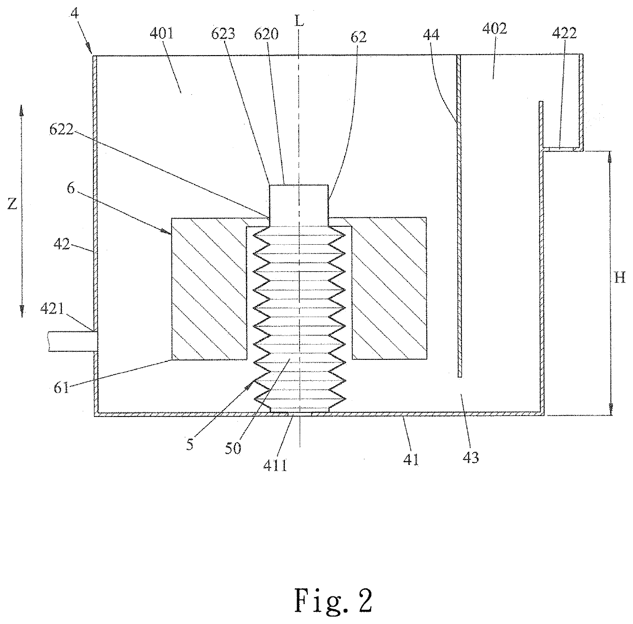
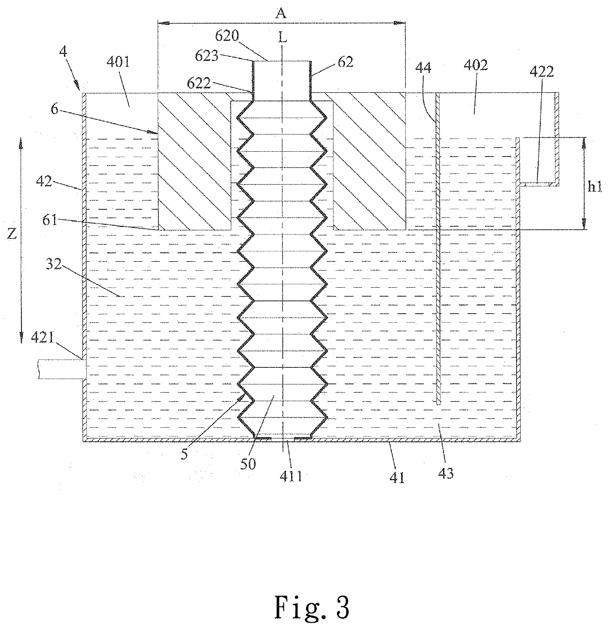
[0020]Referring to FIG. 2, FIG. 3 and FIG. 4, the oil-water separator capable with an oil discharge outlet adjusting spontaneously is adapted to separate a grease 31 from a wastewater 32. In this embodiment, the oil-water separator is provided outside a wastewater pool (not shown) containing the grease 31 and the wastewater 32, and includes a liquid storage tank 4, a telescopic pipe 5, and a floater unit 6.

[0021]The liquid storage tank 4 includes a bottom wall 41, a surrounding wall 42 connected with a periphery of the bottom wall 41 and extending in a height direction Z, and a separator 44 connected with the surrounding wall 42 and defining a passage 43 with the bottom wall 41.

[0022]The bottom wall 41 comprises an oil outlet 411. The oil outlet 411 is adapted to output the grease 31.

[0023]The surrounding wall 42 comprises an inlet 421 and a water outlet 422 spaced apart at an interval. The inlet 421 is adapted to input the grease 31 and the wastewater 32. The water outlet 422 is ad...

second embodiment

[0059]the second embodiment is adapted to be put into a wastewater pool 7 containing the grease 31 and the wastewater 32, and the liquid inlet space 401 is defined in the liquid storage tank 4 only by the surrounding wall 42 and the bottom wall 41. It should be noted that in this embodiment, the water outlet 422 is located lower along the height direction Z adjacent to the bottom wall 41 but higher than the oil outlet 411.

[0060]Therefore, As the second embodiment is put into the wastewater pool 7, the wastewater 32 and the grease 31 are introduced into the liquid inlet space 401 from the inlet 421. The heavier wastewater 32 flows back into the wastewater pool 7 directly from the liquid inlet space 401 through the water outlet 422; and while the lighter grease 31 accumulates in the height direction Z to flood the open end 623 of the isolation member 62, the grease 31 enters the oil-containing space 50 of the telescopic pipe 5 and then is discharged through a discharge pipe 8 connecti...


PUM


Abstract

An oil-water separator with an oil discharge outlet adjusting spontaneously includes a liquid storage tank with grease and wastewater, a telescopic pipe in the liquid storage tank, and a floater unit connected with the telescopic pipe. The liquid storage tank comprises an inlet for grease and wastewater input, and a water outlet for wastewater output. The floater unit comprises at least one floater floating between grease and wastewater, and an isolation member extending in the height direction between the floater and the telescopic pipe. The isolation member fluctuates along with height changes of wastewater and includes an oil discharge outlet for grease entering the telescopic pipe. Therefore, an oil outlet, adjusting height spontaneously, is configured by the at least one floater, such that the overall height is reduced, a sufficient difference of levels of grease and wastewater is generated by the isolation member, thereby improving the oil-water separation effect.

Description

FIELD OF THE INVENTION[0001]The invention relates to an oil-water separator, in particular to an oil-water separator with an oil discharge outlet adjusting spontaneously.BACKGROUND OF THE INVENTION[0002]Referring to FIG. 1, a conventional oil-water separator 1 includes a liquid storage tank 11, and a partition 12 provided in the liquid storage tank 11 and defining a liquid inlet space 111, a liquid outlet space 112 and a passage 113 with the liquid storage tank 11. The liquid inlet space 111 serves to contain grease 21 and wastewater 22. The liquid outlet space 112 serves to contain wastewater 22. The passage 113 connects the liquid inlet space 111 with the liquid outlet space 112. The liquid storage tank 11 includes an inlet 114 for inputting the grease 21 and the wastewater 22 and communicating with the liquid inlet space 111, a water outlet 115 communicating with the liquid outlet space 112, and an oil outlet 116 spaced apart from the water outlet 115 at an interval h in a height...

Claims


Application Information

Patent Timeline
IPC IPC(8): B01D17/02
CPCB01D17/0214B01D17/0208C02F1/40B01D17/12E03F5/16B01D17/02
Inventor CHANG, CHIN-LUNCHANG, CHENG-HANCHANG, SHIH-CHIEH
Owner JENFU MACHINERY
Why Eureka
Try Eureka