
Valve Control and/or Lubrication System

Active Publication Date: 2020-11-12
FMC TECH INC
View PDF0 Cites 5 Cited by
  • Summary
  • Abstract
  • Description
  • Claims
  • Application Information

AI Technical Summary

Benefits of technology

The present invention is a valve control and lubrication system for use in frac operations. The system uses a single hose set to connect all valves, which reduces the time and labor required to setup the frac operation and minimizes hose cost and trip hazards at the frac site. The system also includes identifying means for designating the location and function information of each valve and determining means for reading the tags. The identifying means may comprise machine-readable tags connected to each control unit, which may be easily removable. Overall, the system simplifies the setup process for frac operations and improves operational efficiency.

Problems solved by technology

However, such a large number of hoses are very costly, can be time consuming to install and pose trip hazards to personnel at the frac site.
Also, due to the relatively high pressures employed in fracking operations, a possibility exists that the fracking fluid will enter the valve cavity and interfere with the ability of the valve to seal properly.
However, over time the lubricant tends to break down and become depleted.
However, this is a time consuming process and exposes the operator to the dangers inherent in the areas surrounding the frac trees.
Once again, however, this arrangement requires the use of a large number of hoses, which is costly, can be time consuming to install and pose trip hazards to personnel at the frac site.

Method used


Image

  • Valve Control and/or Lubrication System
  • Valve Control and/or Lubrication System
  • Valve Control and/or Lubrication System

Examples


Embodiment Construction

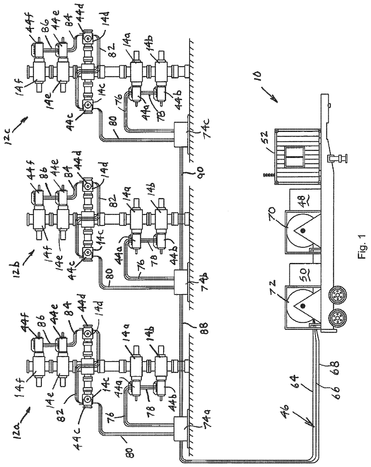
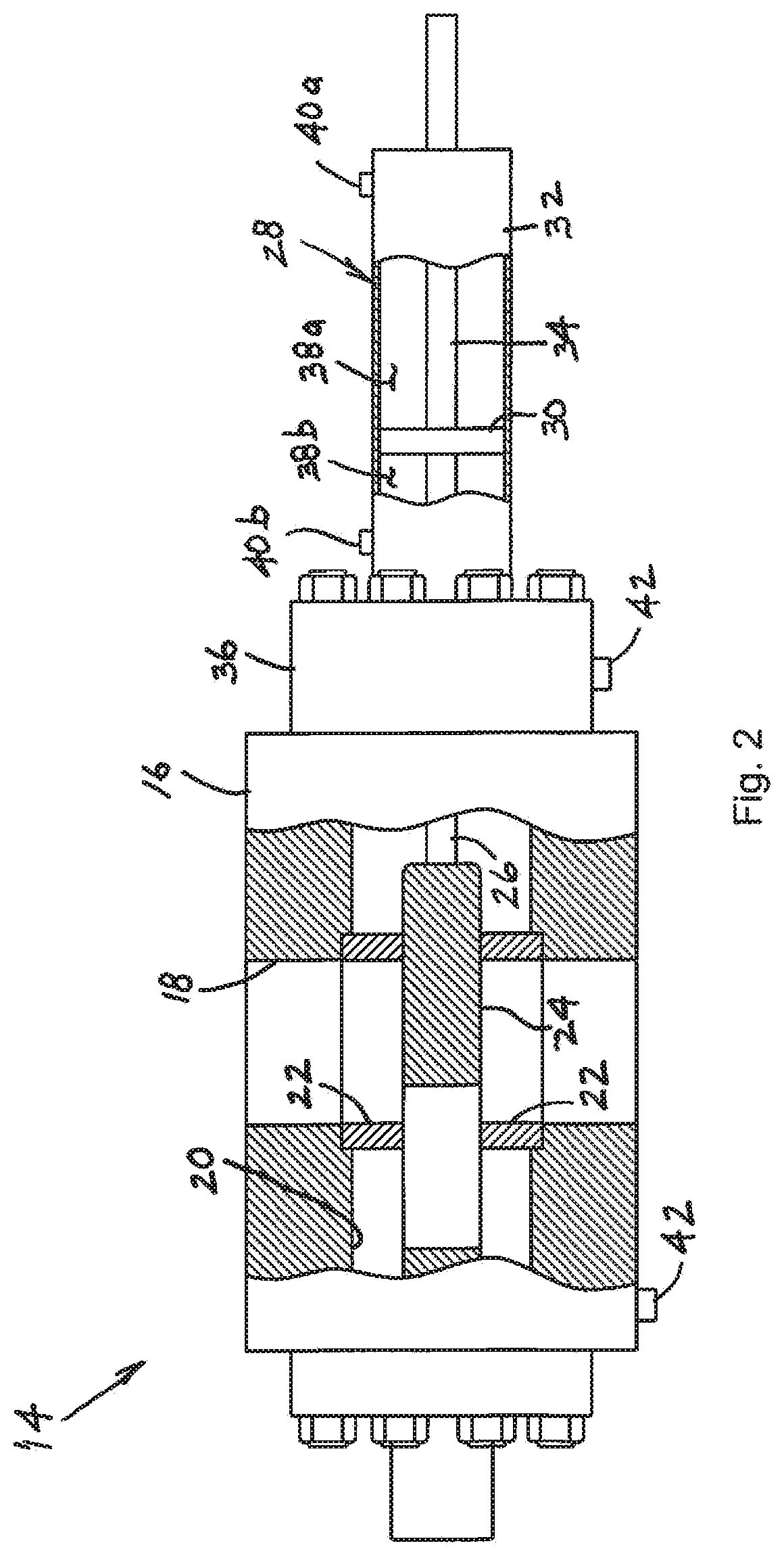
[0030]In general, the present disclosure is directed to a system for controlling and / or lubricating a plurality of valves which are mounted on a number of Christmas trees and / or manifolds. The system is particularly applicable to valves of the type which comprise a hydraulic actuator which is operated by hydraulic pressure from a hydraulic pressure source and / or a lubricant inlet which is connected to an interior portion of the valve that is configured to receive a lubricant from a lubricant source.

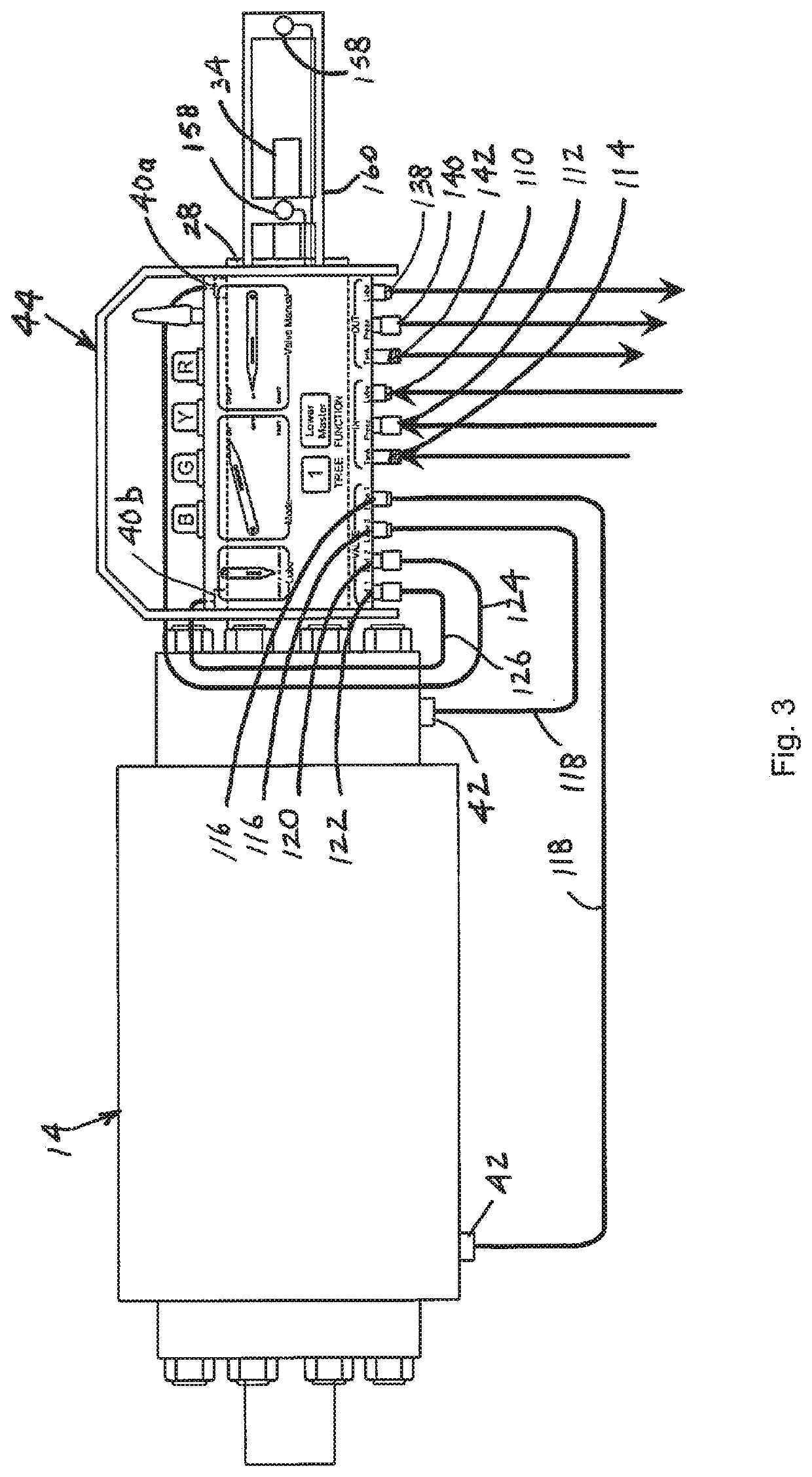
[0031]In one embodiment of the disclosure, the system includes a plurality of control units, each of which is associated with a respective valve, and each of which comprises at least one of a hydraulic pressure line which is connectable to the hydraulic pressure source and a lubricant line which is connectable to the lubricant source. Each control unit also includes at least one of a hydraulic port and a lubricant port; at least one of a hydraulic conduit connecting the hydraulic port to ...


PUM


Abstract

A system for operating and / or lubricating a plurality of valves which are mounted on a number of Christmas trees and which each include a hydraulic actuator which is operated by hydraulic pressure from a hydraulic pressure source and a lubricant inlet which is connected to an interior portion of the valve that is configured to receive a lubricant from a lubricant source. The system includes a plurality of control units, each of which is associated with a respective valve and each of which has at least one of a hydraulic pressure line which is connectable to the hydraulic pressure source and a lubricant line which is connectable to the lubricant source. Each control unit further includes at least one of a hydraulic port and a lubricant port, and the system further includes at least one of a hydraulic conduit which is connected between the hydraulic port and the hydraulic actuator and a lubricant conduit which is connected between the lubricant port and the lubricant inlet. Each control unit also includes at least one of a hydraulic activator for selectively connecting the hydraulic pressure line to the hydraulic port and a lubricant activator for selectively connecting the lubricant line to the lubricant port. Each control unit is operable to selectively connect the hydraulic pressure source to the hydraulic actuator to thereby operate the valve and / or to selectively connect the lubricant source to the lubricant inlet to thereby communicate lubricant into the interior portion of the valve.

Description

FIELD OF THE DISCLOSURE[0001]The present disclosure is directed to a system for controlling and / or lubricating a plurality of flow control valves, such as valves of a type which are used on frac trees at a well fracturing site. In particular, the disclosure is directed to a system which communicates the hydraulic fluid used to actuate the valves and / or the lubricant used to lubricate the valves to the frac trees over a single hose set, thereby greatly reducing the number of hydraulic fluid and lubricant hoses which otherwise would be required at the frac site.BACKGROUND OF THE DISCLOSURE[0002]Typical prior art well fracturing operations employ a number of frac trees which each include a plurality of hydraulically operated valves. These valves include valve actuators which are operated by hydraulic pressure that is often supplied by a centrally located hydraulic pressure unit (HPU). Each valve actuator normally comprises two piston chambers which are each connected to the HPU via a r...

Claims


Application Information

Patent Timeline
IPC IPC(8): F16N7/38F16N3/02F16N29/04G05D7/06
CPCF16N7/385E21B34/02F16K3/36F16N2270/70E21B43/26E21B43/2607F16K3/0254F16K31/122
Inventor ZERKUS, JAMES MICHAELRAYMOND, STEVEN DORNELLMACHADO, THIAGO GUIMARÃESPILLAI, RAJEEV RAJAN
Owner FMC TECH INC
Learn More