
Vehicle seat structure

Active Publication Date: 2020-12-10
MAZDA MOTOR
View PDF0 Cites 0 Cited by
  • Summary
  • Abstract
  • Description
  • Claims
  • Application Information

AI Technical Summary

Benefits of technology

The present invention provides a vehicle seat structure that can make the seat more comfortable for the occupant by reducing the difference in rigidity between the left and right parts of the seat. This improves the traveling experience of the occupant.

Problems solved by technology

Traveling comfort actually experienced by a seated occupant may not be improved, even if characteristics of a frame, a cushion member, and the like of a vehicle seat are individually improved.

Method used


Image

  • Vehicle seat structure
  • Vehicle seat structure
  • Vehicle seat structure

Examples


first embodiment

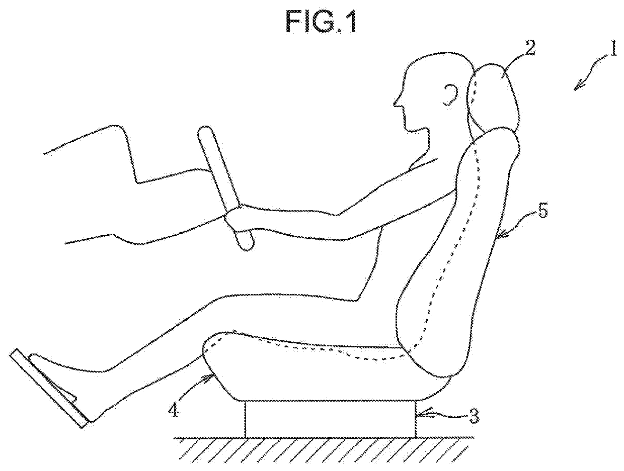
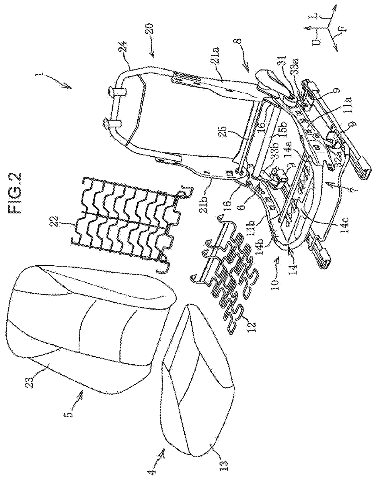
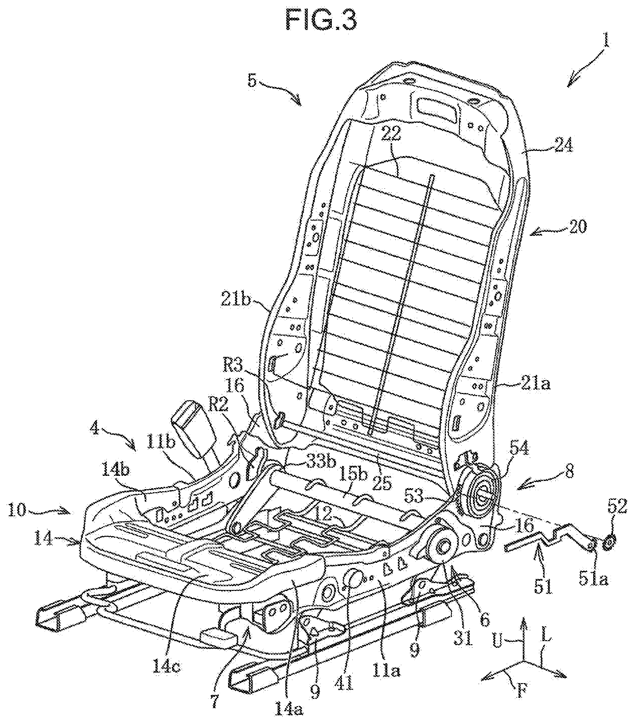
[0024]A first embodiment according to the present invention is described with reference to FIGS. 1 to 7.

[0025]As illustrated in FIG. 1, a vehicle seat 1 according to the first embodiment includes, as main constituent elements, a head rest for receiving the head of a seated occupant, a leg mechanism 3 for fixing the seat 1 to a passenger compartment floor, a seat cushion 4 for supporting a part (buttock) corresponding to the ischial bone of the seated occupant, and a seat back 5 for supporting a part (back) corresponding to the spine (backbone) of the seated occupant.

[0026]The seat 1 includes, as a posture changing mechanism for adjusting a seated posture of the occupant, a lifter mechanism 6 capable of changing a height position of the seat cushion 4, a tilt mechanism 7 capable of changing a height position of a front end of the seat cushion 4, and a reclining mechanism 8 capable of changing a tilt angle of the seat back 5.

[0027]In the following description, “front”, “rear”, “left”,...

second embodiment

[0100]Next, a vehicle seat 1A according to a second embodiment of the present invention is described with reference to FIGS. 8 to 10. In FIGS. 8 to 10, members similar to those in the first embodiment are indicated with the same reference numbers, and detailed description thereof is omitted.

[0101]Whereas, in the first embodiment, manually operated posture changing mechanisms (6 to 8) are employed, in the second embodiment, electrically operated posture changing mechanisms (6A to 8A) to be driven by electric motors M1 to M3 are employed.

[0102]As illustrated in FIGS. 8 to 10, the lifter mechanism 6A includes an operation portion 31A to be operated by an occupant, the motor M1 to be driven in response to an operation of the operation portion 31A, a pinion 31a, and a 4-link mechanism. The motor M1 is disposed on an outer surface (left surface) of the left side frame 11a, and is able to drive and rotate the pinion 31a.

[0103]The tilt mechanism 7A includes an operation portion 41A to be o...


PUM


Abstract

A vehicle seat structure includes: a first side frame (11a) extending in a front-rear direction along one side portion of a seat cushion (4); a second side frame (11b) extending in the front-rear direction along the other side portion of the seat cushion (4); posture changing mechanisms (6, 7) mounted on the first side frame (11a) and capable of changing the posture of the seat cushion (4), and reinforcement members (R1, R2) provided at a portion of the second side frame (11b) where the reinforcement members (R1, R2) overlap the posture changing mechanisms (6, 7) in a side view.

Description

TECHNICAL FIELD[0001]The present invention relates to a vehicle seat structure.BACKGROUND ART[0002]Conventionally, various techniques relating to characteristics of a frame, a cushion member, and the like of a vehicle seat have been proposed in order to enhance seating comfort of a seated occupant, traveling comfort in a vehicle, and the like.[0003]Patent Literature 1 discloses a seat cushion member support mechanism including a front link connected to a front torsion bar, and a rear link connected to a rear torsion bar. The front link and the rear link are pivotally moved in opposite directions, when a load of a predetermined value or larger is applied thereto. A damper is disposed between a lower portion of the front link and a lower portion of the rear link. The damper expands or contracts, when a load of a predetermined value or larger is applied thereto, and generates a damping force. On the other hand, the damper does not expand or contract, when a load smaller than the predet...

Claims


Application Information

Patent Timeline
IPC IPC(8): B60N2/10B60N2/68B60N2/16
CPCB60N2/68B60N2/10B60N2/16B60N2002/0208B60N2/02B60N2002/924B60N2/22
Inventor SUZUKI, TAKASHINONOWAKI, KOJISAKAI, SHINKOBAYASHI, SHIGERUIWAKURA, HIROYUKI
Owner MAZDA MOTOR
Learn More