Method for dip-coating a metal strip

a metal strip and dip coating technology, applied in the field of methods, can solve the problems of deterioration or breakdown of equipment, malfunction of overflow, corrosion of the snout, etc., and achieve the effect of reducing the impact on production, facilitating the correct positioning of overflow, and simplifying and more reliable overflow tuning

Active Publication Date: 2020-12-24
ARCELORMITTAL INVESTIGACION Y DESARROLLO SL
View PDF5 Cites 2 Cited by
  • Summary
  • Abstract
  • Description
  • Claims
  • Application Information

AI Technical Summary

Benefits of technology

[0007]Consequently, there is a need to find a simpler and more reliable overflow tuning device, as well as one easing its replacement. The solution should also ease the correct positioning of the overflow. Furthermore, it would be very advantageous, if the overflow could be removed without cutting the strip so it remains threaded and reduces the impact on the production.

Problems solved by technology

Moreover, while in use, the equipment deteriorates or breaks down due to various effects.
For example, the immersed part of the snout is subject to corrosion, the pump or the level indicator of the overflow happens to malfunction.
In order to overcome those issues, some part of the snout or the overflow needs to be replaced or repaired, such operations lead to the strip cut, a decrease in productivity and higher cost of manufacturing.
However, by using the above equipment, the right setting of the overflow is complex and, if not handled properly, may lead to inadequate positioning.
The setting complexity is due to the difficulties of levelling both sides of the overflow by making an horizontal displacement without vertical displacement.
Moreover, this needs lot of mechanisms leading up to higher probability of failure.

Method used


Image

  • Method for dip-coating a metal strip
  • Method for dip-coating a metal strip
  • Method for dip-coating a metal strip

Examples


example 1

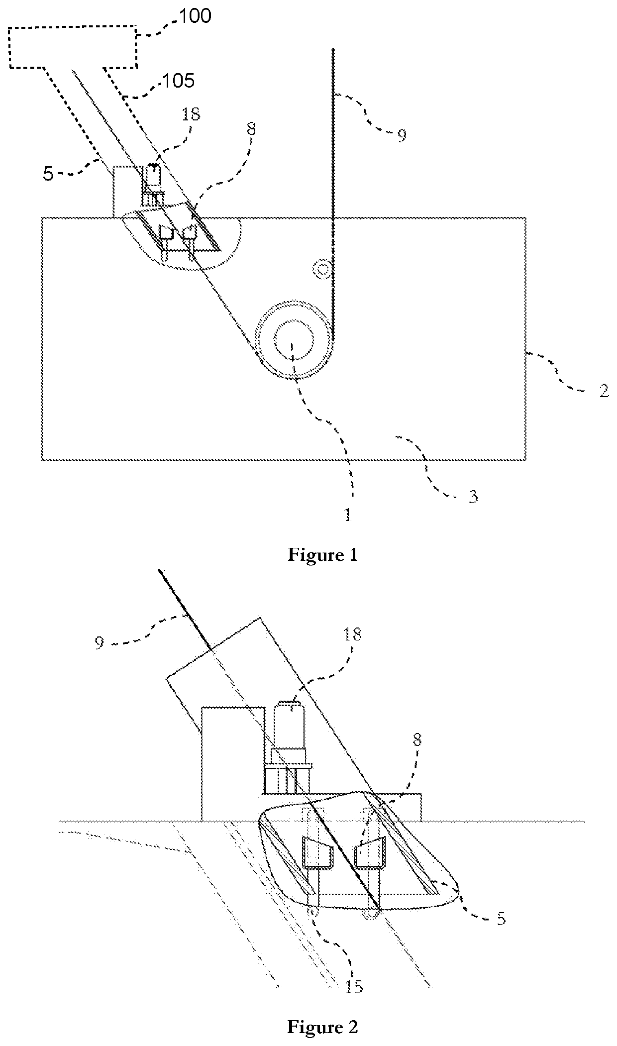
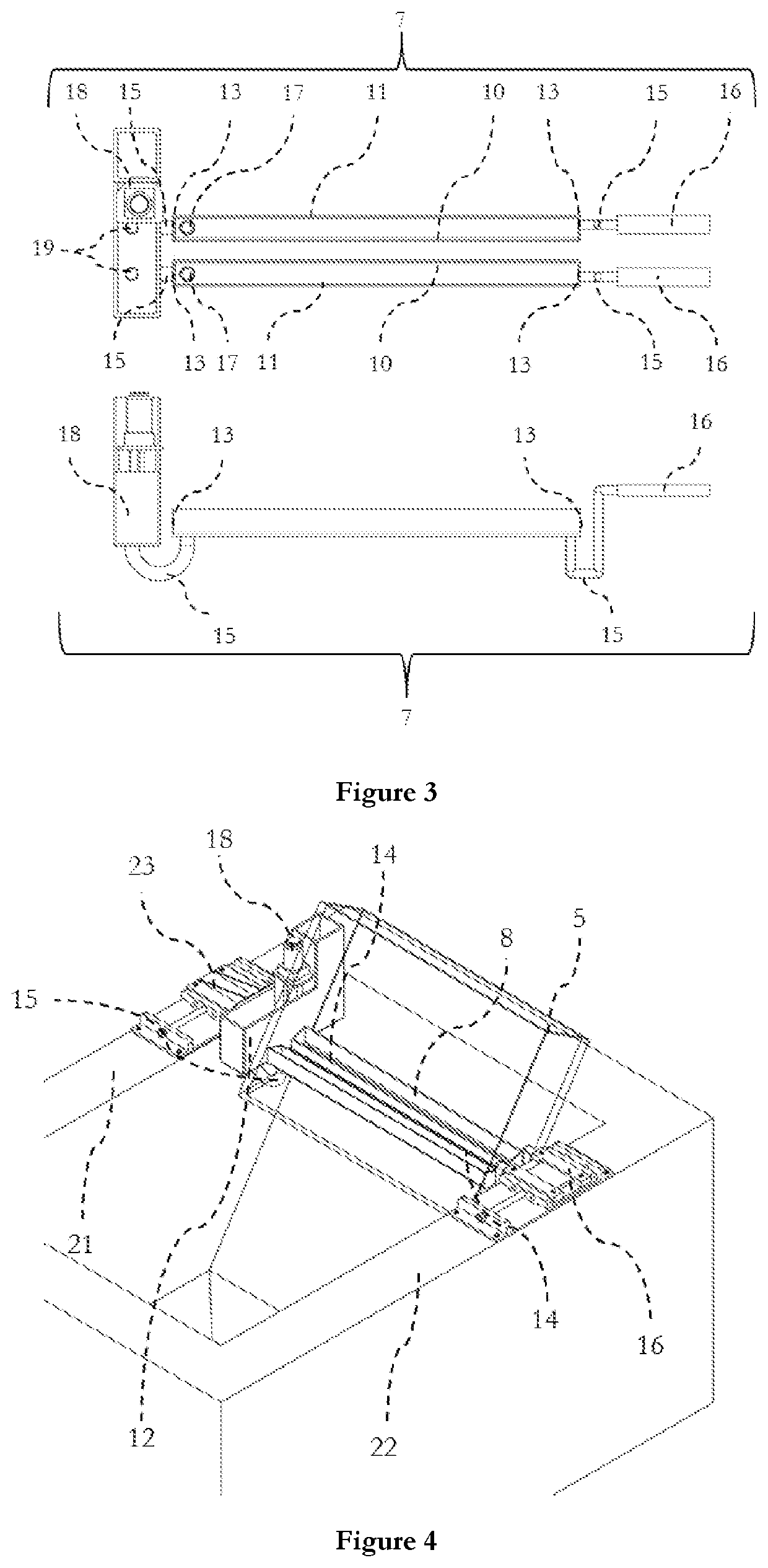
[0061]In a particular embodiment, using the teaching of the present invention, the bath length is of 3900 mm and its width is of 2720, the snout length is of 2300 mm and 525 mm wide permitting the passage of a 1800 mm wide strip. The sabot height is of 1283 mm when in use, the The tray is of 2200 mm long and 150 mm wide and high for the external wall and 100 mm high for the internal wall. The shiftable system 23 can be shifted on 420 mm along the bath width and is screwed by four screws to the bath side wide of 500 mm, two at each extremity. The shiftable system 23 on which the supports are attached is 500 mm long. The upper part of the internal wall is 120 mm below the bath side while the external wall is 70 mm below the bath side. The tray is fixed on one side to the shiftable system by means of a two 500 mm long plate screwed two times each and on the other side, the one containing the level indicator, the shiftable system is fixed to the level indicator system by three screws al...

example 2

[0062]In a preferred embodiment, the classical overflow (like in FR 2 816 639) has been replaced by the overflow described in this patent.

[0063]With the classical overflow, the steps necessary to change an overflow are generally the followings:

[0064]A) Stop the line,

[0065]B) Cooling (wait),

[0066]C) Remove bath hardware,

[0067]D) Lower the pot,

[0068]E) Move the pot to garage position,

[0069]F) Install platform,

[0070]G) Cut the strip,

[0071]H) Remove the snout (with the overflow),

[0072]I) Install the new snout (with the overflow),

[0073]J) Treading of the strip,

[0074]K) Weld the strip,

[0075]L) Remove the platform,

[0076]M) Move the pot from the garage position,

[0077]N) Raise the pot,

[0078]O) Install bath hardware,

[0079]P) Inert the snout,

[0080]Q) Heat up,

[0081]R) Restart the line.

[0082]This procedure takes about twenty-four hours when the classical overflow is used. Whereas when the removable overflow is mounted, only the steps A, C, D, N, O, P, Q and R are done. Thus the replacement of th...


PUM

PropertyMeasurementUnit
distanceaaaaaaaaaa
temperaturesaaaaaaaaaa

Abstract

Equipment for the continuous hot dip-coating of a metal strip 9 including an annealing furnace, a tank 2 containing a liquid metal bath 3, a snout connecting the annealing furnace and tank 2, through which the metal strip 9 runs in a protective atmosphere and the lower part of the snout, the sabot 5, is at least partly immersed in the liquid metal bath 3 in order to define with the surface of the bath, and inside this snout, a liquid seal 6, an overflow 7 not connected to the snout, the overflow 7 including at least one tray 8, placed in the vicinity of the strip 9 when entering the liquid metal bath 3 and encompassed by liquid seal 6.

Description

[0001]The present invention relates to equipment for the hot dip-coating of a metal strip comprising an annealing furnace, a tank containing a liquid metal bath, a snout connecting the annealing furnace and the tank as well as an overflow separated from the snout. In other words, the snout has one side at the end of the annealing furnace, usually high up, and the other one a bit under the liquid metal bath surface, creating a seal. Such a positioning aims to protect the metal strip against oxidation from the annealing furnace until it reaches the liquid metal bath. The overflow is located at the surface of the liquid metal bath encompassed by the snout.BACKGROUND[0002]During the coating process, the entering position of the strip into the bath changes over time due to different factors, e.g. changes in the strip entry position, and thus affects the optimal position of the overflow. Consequently, the overflow needs to be shifted and moved to the optimal position during the process.[0...

Claims


Application Information

Patent Timeline
Patent Type & Authority Applications(United States)
IPC IPC(8): C23C2/00C21D9/56C23C2/40C23C2/06C23C2/02C23F17/00
CPCC23F17/00C23C2/003C23C2/02C23C2/40C21D9/562C21D9/561C23C2/06C23C2/0222C23C2/0034C23C2/004C23C2/0038C23C2/50C23C2/00344C23C2/022C23C2/0224
Inventor GARCIA MARTINO, ANGELGARCIA-CHAPA, INOCENCIO
Owner ARCELORMITTAL INVESTIGACION Y DESARROLLO SL
Why Eureka
Try Eureka