Motor branch circuit health monitoring method

a health monitoring and branch circuit technology, applied in the direction of polyphase induction motor starters, electrical equipment, control systems, etc., can solve problems such as faults in distribution transformers, unbalanced distribution of single phase loads on the same branch circuit, and voltage and currents that may occasionally become unbalanced

Active Publication Date: 2020-12-24
SCHNEIDER ELECTRIC USA INC
View PDF0 Cites 4 Cited by
  • Summary
  • Abstract
  • Description
  • Claims
  • Application Information

AI Technical Summary

Problems solved by technology

However, voltages and currents may occasionally become unbalanced in the three-phases of the power supply lines.
For example, such imbalances can result from faults in a distribution transformer or unbalanced distribution of single phase loads on the same branch circuit, such as a momentary current draw by starting-up large electr

Method used


Image

  • Motor branch circuit health monitoring method
  • Motor branch circuit health monitoring method
  • Motor branch circuit health monitoring method

Examples


Embodiment Construction

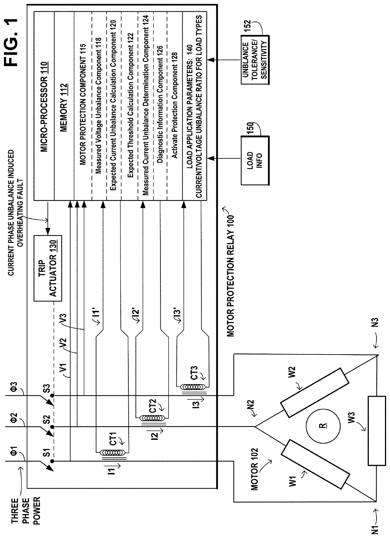
[0019]Voltages and currents within three-phase induction motors may occasionally become unbalanced in the three-phases of the power supply lines, e.g., as a result of faults in a distribution transformer or unbalanced distribution of single phase loads on the same branch circuit, such as a momentary current draw by starting-up large electrical machinery or by a heavy arc welder. A three-phase motor may continue to operate with unbalanced voltages and currents, however its efficiency is reduced by both increased current and increased resistance due to heating. The stator winding with the highest current will have the greatest overheating, resulting in deterioration of the insulation of the stator winding. During power supply unbalance, currents flow through the stator windings in a negative sequence direction, resulting in induction of negative sequence voltage in the rotor coils, abnormal current flow, and overheating.

[0020]Under conditions of balanced voltages and currents, where t...


PUM


Abstract

Techniques for monitoring the health of a three-phase induction motor are provided. An expected threshold value is calculated as a function of an expected ratio of current unbalance to voltage unbalance for the three-phase motor. Embodiments determine whether a measured current unbalance exceeds the expected threshold value. Responsive to the measured current unbalance exceeding the expected threshold value, a remedial action may be taken, such as generating diagnostic information or activating one or more protection operations for the three-phase induction motor.

Description

BACKGROUNDTechnical Field[0001]The present disclosure relates to motor protection and, more specifically, to techniques for dynamically setting and applying a current imbalance threshold for motor protection, based on measures of voltage imbalance.Description of the Related Art[0002]Three-phase induction motors have three windings in the stator, which when connected to power lines supplying alternating voltage and current in three-phases, cause magnetic flux to rotate in a positive sequence direction within the stator. The rotor within the stator has an arrangement of closed-loop coils that can rotate and have current induced in them by the rotating magnetic field of the stator windings, forcing the rotor to rotate in the same direction as the positive sequence direction of the magnetic flux within the stator.As long as the power supply voltages and currents are equal in magnitude in the three-phases, i.e. balanced, the magnetic flux rotates in the positive sequence direction within...

Claims


Application Information

Patent Timeline
IPC IPC(8): H02P1/26
CPCH02P1/26H02P29/024
Inventor JEFFERIES, KEVIN M.EDWARDS, BENJAMIN W.FREEMAN, ALAN E.WEILER, RICHARD KWHITE, MATTHEW L.
Owner SCHNEIDER ELECTRIC USA INC
Why Eureka
Try Eureka