Linking device for an exoskeleton structure facilitating the carrying of loads while walking or running

a technology of linking device and exoskeleton, which is applied in the direction of manufacturing tools, mechanical equipment, gearing, etc., can solve the problems of reduced mobility of infantrymen, increased metabolic output, and muscular-skeletal problems

Active Publication Date: 2020-12-31
SAFRAN ELECTRONICS & DEFENSE +1
View PDF0 Cites 5 Cited by
  • Summary
  • Abstract
  • Description
  • Claims
  • Application Information

AI Technical Summary

Benefits of technology

[0022]during the oscillating phase, when the foot is no longer in contact with the ground, the mechanical leg assembly is free of any load generated by the backpack, so that the oscillating foot moves freely.
[0023]Moreover, when the user is standing immobile, the mechanical leg assemblies of the exoskeleton structure are in contact with the ground simultaneously. The proposed linking device allows sharing the load generated by the backpack by distributing it over both mechanical leg assemblies.

Problems solved by technology

The mass of the backpack can strongly reduce the mobility of the infantryman and cause a greater metabolic output.
Moreover, the backpack generally rests on the shoulders or on the hips of the user, which can generate muscular-skeletal problems at the shoulders, skin pressure, or be the source of neurological symptoms due to nerve compression (tingling sensations).
These solutions do not however allow the user to be completely relieved.
However, known exoskeleton structures (sometimes called “walking robots”) generate very significant bulk and reduce the mobility of the user.
This load consequently has a tendency to oppose the movements of the feet of the user when walking, in particular when the user moves his foot off the ground.

Method used


Image

  • Linking device for an exoskeleton structure facilitating the carrying of loads while walking or running
  • Linking device for an exoskeleton structure facilitating the carrying of loads while walking or running
  • Linking device for an exoskeleton structure facilitating the carrying of loads while walking or running

Examples


first embodiment

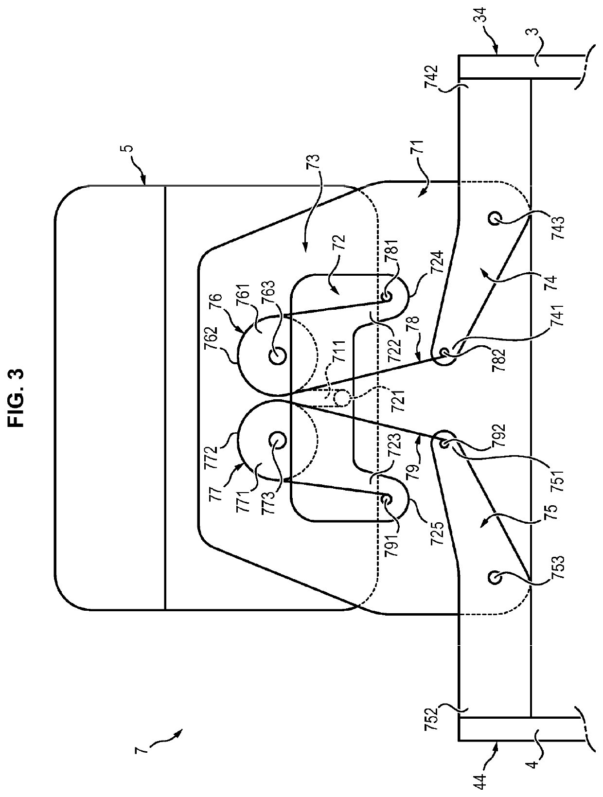
[0072]FIGS. 3 and 4 show schematically a linking device 7 conforming to a first embodiment, connecting the mechanical back assembly 5 to the lumbar belt 2 and to the mechanical leg assemblies 3 and 4.

[0073]The linking device 7 comprises a support 71, an input part 72, a transmission device 73, a first connecting link 74 and a second connecting link 75.

[0074]The support 71 is attached to the lumbar belt 2.

[0075]The input part 72 is connected to the mechanical back assembly 5. The input part 72 is mounted sliding with respect to the support 71 by means of a slider 711 and of a cylindrical pin 721 capable of sliding inside the slider 711 and turning with respect to the slider 711. More precisely, the pin 721 is mounted fixedly on the input part 72 and the slider 711 is mounted fixedly on the support 71. The pin 721 and the slider 711 thus allow translation of the input part 72 with respect to the support 71 in a substantially vertical direction when the user holds himself in a standing...

second embodiment

[0100]FIG. 6 shows schematically a linking device 7 conforming to a

[0101]Just as in the first embodiment, the linking device 7 comprises a support 71, an input part 72, a transmission device 73, a first connecting link 74 and a second connecting link 75.

[0102]The support 71 is attached to the lumbar belt 2.

[0103]The input part 72 is connected to the mechanical back assembly 5. The input part 72 is mounted sliding with respect to the support 71 by means of a slider 711 and of a pin 721 capable of sliding inside the slider 711 and turning with respect to the slider 711.

[0104]In this second embodiment, the input part 72 has the general shape of an inverted T with a first branch 722 and a second branch 723. The first branch 722 has a first end 724 and the second branch 723 has a second end 725.

[0105]The transmission device 73 comprises a first pulley 76, a second pulley 77, a third pulley 86, a fourth pulley 87, a first cable 78, a second cable 79, a third cable 88 and a fourth cable 89...


PUM


Abstract

A linking device for an exoskeleton structure is provided. The device an input part mounted in rotation with respect to a support, and a transmission device that when a load is applied to the input part to pivot the input part in a first direction of rotation, the transmission device transmits to a first connecting link a force to pivot the first connecting link to transfer the load to a first mechanical leg assembly and unload a second mechanical leg assembly of the exoskeleton structure, and when a load is applied to the input part to pivot the input part in a second direction of rotation opposite to the first direction, the transmission device transmits to a second connecting link a force to pivot the second connecting link to transfer the load to a second mechanical leg assembly and unload the first mechanical leg assembly.

Description

FIELD OF THE INVENTION[0001]The invention relates to a linking device for an exoskeleton structure, and an exoskeleton structure comprising a device of this type.PRIOR ART[0002]In the military field, infantrymen are currently equipped with backpacks allowing them to transport equipment. When the infantrymen are carrying out prolonged missions, the mass of the backpack can reach 50 kilograms. The mass of the backpack can strongly reduce the mobility of the infantryman and cause a greater metabolic output.[0003]Moreover, the backpack generally rests on the shoulders or on the hips of the user, which can generate muscular-skeletal problems at the shoulders, skin pressure, or be the source of neurological symptoms due to nerve compression (tingling sensations).[0004]Current solutions consist of distributing the mass of the backpack both on the shoulders by means of straps and on the hips by means of a ventral belt. These solutions do not however allow the user to be completely relieved....

Claims


Application Information

Patent Timeline
Patent Type & Authority Applications(United States)
IPC IPC(8): B25J9/00B25J9/10F16H19/06A61H1/02A61H3/00
CPCF16H19/06B25J9/0006A61H2201/163A61H1/0262B25J9/104A61H1/0292A61H3/00A61H2003/007B25J9/00B25J9/0009B25J9/106
Inventor BILODEAU, KATIASOUCY, FRANCISCOZOSO, NATHANIELBAPTISTA, JONATHANGRENIER, JORDANE
Owner SAFRAN ELECTRONICS & DEFENSE
Why Eureka
Try Eureka