Projection optical system and projector
- Summary
- Abstract
- Description
- Claims
- Application Information
AI Technical Summary
Benefits of technology
Problems solved by technology
Method used
Image
Examples
example 1
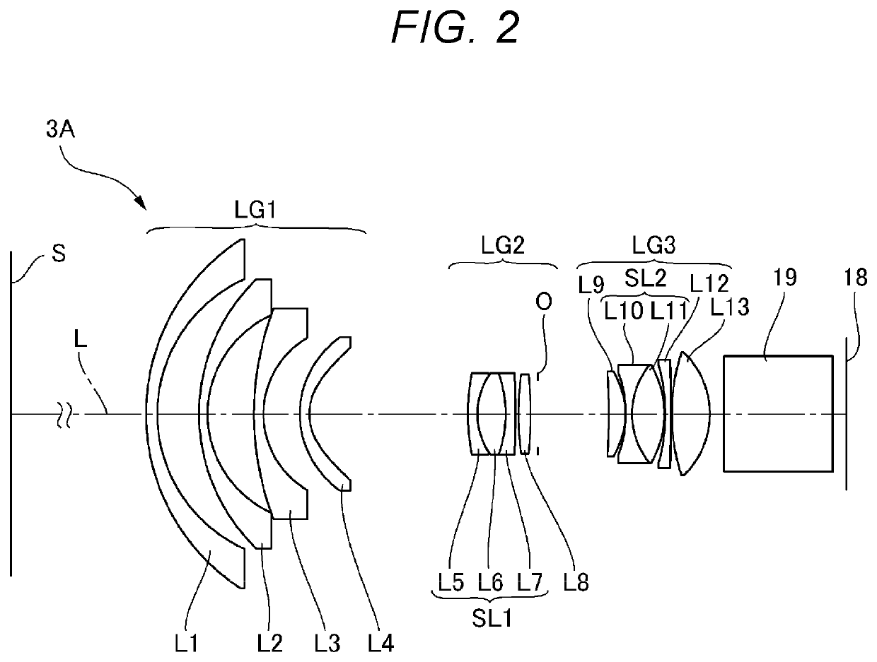
[0050]FIG. 2 is a configuration diagram of the projection optical system according to Example 1. A projection optical system 3A according to the present example is formed of the following components sequentially arranged from the enlargement side: a first lens group LG1 having negative power; a second lens group LG2 having positive power; an aperture stop O; and a third lens group LG3 having positive power. The projection optical system 3A includes 13 lenses in total. When the projection distance of the projection optical system 3A is changed, the space between the lens group LG1 and the lens group LG2 is changed for focusing.
[0051]The light modulator 18 is located in the reduction-side conjugate plane of the projection optical system 3A. The screen S is located in the enlargement-side conjugate plane of the projection optical system 3A. The projection optical system 3A includes the cross dichroic prism 19 between the light modulator 18 and a reduction-side first lens located in a p...
example 2
[0084]FIG. 8 is a configuration diagram of the projection optical system according to Example 2. A projection optical system 3B according to the present example is formed of the following components sequentially arranged from the enlargement side: a first lens group LG1 having negative power; a second lens group LG2 having positive power; an aperture stop O; and a third lens group LG3 having positive power. The projection optical system. 3B includes 12 lenses in total. The projection optical system 3B includes the cross dichroic prism 19 between the light modulator 18 and a reduction-side first lens located in a position closest to the reduction side. The reduction-side first lens is the twelfth lens L12. When the projection distance of the projection optical system 3B is changed, the space between the entire optical system and the cross dichroic prism 19 is changed for focusing.
[0085]The first lens group LG1 includes three negative lenses. The three negative lenses are each a singl...
example 3
[0112]FIG. 14 is a configuration diagram of the projection optical system according to Example 3. A projection optical system 3C according to the present example is formed of the following components sequentially arranged from the enlargement side: a first lens group LG1 having negative power; a second lens group LG2 having positive power; an aperture stop O; and a third lens group LG3 having positive power. The projection optical system 3C includes 11 lenses in total. The projection optical system. 3C includes the cross dichroic prism 19 between the light modulator 18 and a reduction-side first lens located in a position closest to the reduction side. The reduction-side first lens is the eleventh lens L11. When the projection distance of the projection optical system 3C is changed, the space between the entire optical system and the cross dichroic prism 19 is changed for focusing.
[0113]The first lens group LG1 is formed of four negative lenses. The four lenses are each a single len...
PUM
 Abstract
Description
Claims
Application Information
 - R&D
- Intellectual Property
- Life Sciences
- Materials
- Tech Scout
- Unparalleled Data Quality
- Higher Quality Content
- 60% Fewer Hallucinations
Browse by: Latest US Patents, China's latest patents, Technical Efficacy Thesaurus, Application Domain, Technology Topic, Popular Technical Reports.
© 2025 PatSnap. All rights reserved.Legal|Privacy policy|Modern Slavery Act Transparency Statement|Sitemap|About US| Contact US: help@patsnap.com


