
Image processing apparatus, image processing method, program for processing image and recording medium storing program

a technology for processing apparatus and recording media, applied in the field of image processing apparatus for processing image pickup signals, can solve the problems of neither the means, nor the image displayed in the output image display section b>4/b> is distorted, and achieve the effect of correcting distortion aberration, suppressing jaggy occurrence, and reducing the probability of occurren

Inactive Publication Date: 2005-10-20
SHARP KK
View PDF3 Cites 16 Cited by
  • Summary
  • Abstract
  • Description
  • Claims
  • Application Information

AI Technical Summary

Benefits of technology

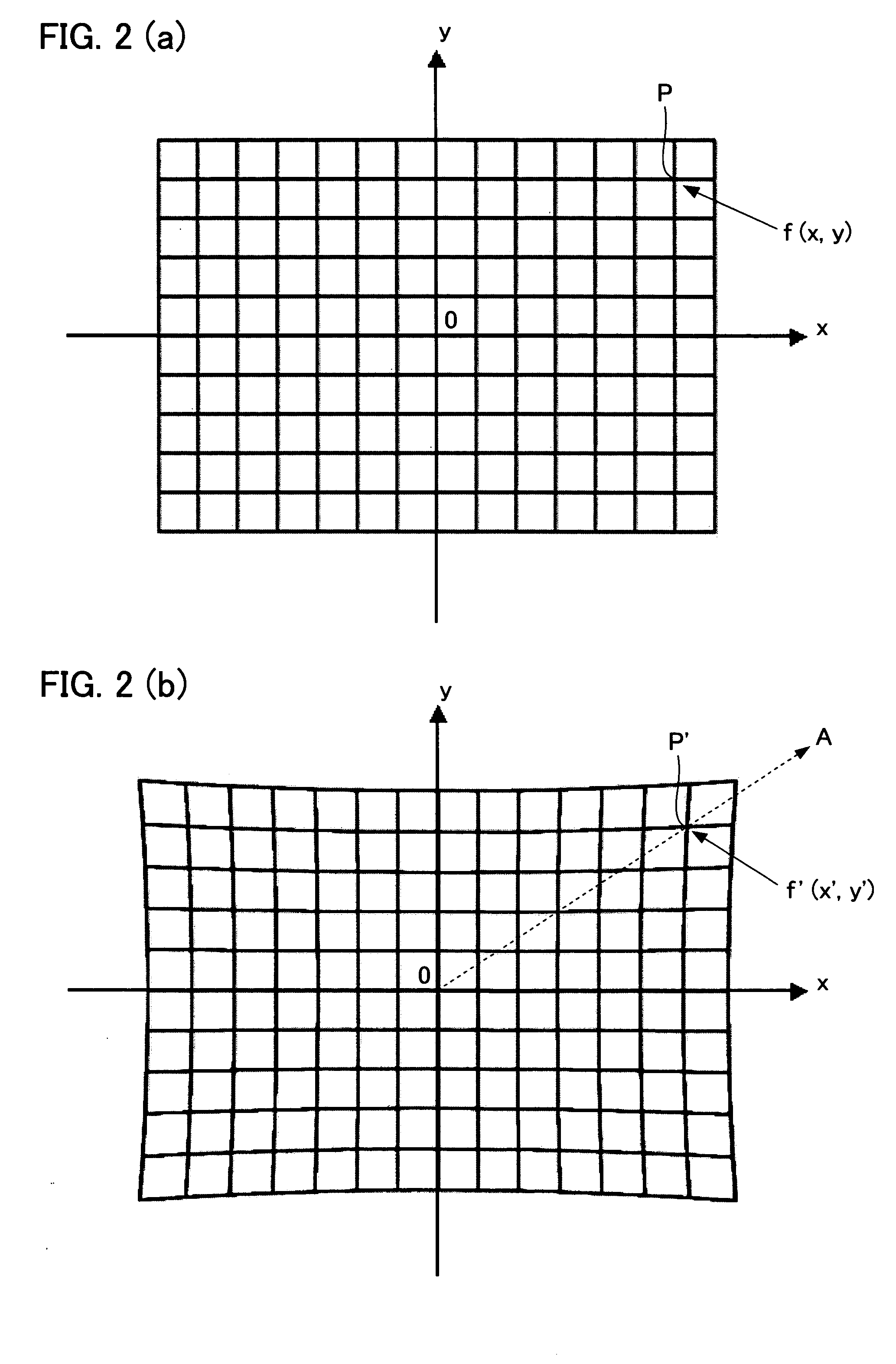
[0024] the signal processing means (i) performs a correction of distortion aberration due to an imaging optical system with respect to an image pickup signal obtained via the imaging optical system, by changing in radial directions, a pixel position of each pixel in a target image corresponding to the image pickup signal obtained via the imaging optical system when a pixel position corresponding to an optical axis of the imaging optical system is set as a center, the pixel position being located substantially at a center of a target image subjected to the correction, according to a distance from the pixel position corresponding to the optical axis, and (ii) suppresses an occurrence of jaggy in a resulting corrected image.
[0037] According to the foregoing structure, the distortion aberration can be corrected by changing each pixel position only radial directions from a pixel position corresponding to the optical axis of the imaging optical system, while suppressing an occurrence of jaggy in a resulting corrected image.

Problems solved by technology

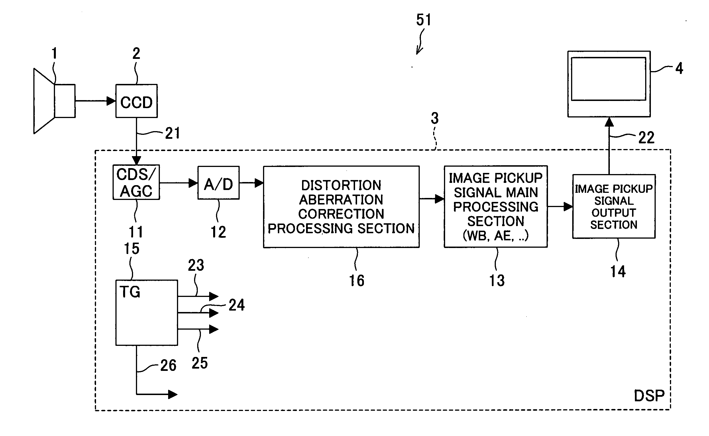
However, the foregoing conventional solid-state image pickup apparatus has a problem in that an image displayed in the output image display section 4 is distorted due to distortion aberration as occurred via the imaging optical system.
However, the patent document 2 does not address the problem of jaggy which is likely to occur in the process of correcting the distortion aberration, nor the means for preventing the problem of jaggy generated in the corrected image.

Method used


Image

  • Image processing apparatus, image processing method, program for processing image and recording medium storing program
  • Image processing apparatus, image processing method, program for processing image and recording medium storing program
  • Image processing apparatus, image processing method, program for processing image and recording medium storing program

Examples


first embodiment

[0073] In the preferred embodiment of the present invention, the distortion aberration due to the imaging optical system, in the image pickup signal (CCD output signal) transferred from the solid-state image pickup element, is corrected by the digital signal processing section (DSP) and jaggy which is likely to occur in the process of correcting the distortion aberration is suppressed by performing the filtering process, to realize desirable image.

[0074] In the following, a preferred embodiment of the present invention will be explained in reference to the attached figures. For convenience in explanations, members having the same functions as those of the conventional structure as explained under the section “Background of the Invention” will be designated by the same reference numerals, and thus the descriptions thereof shall be omitted here.

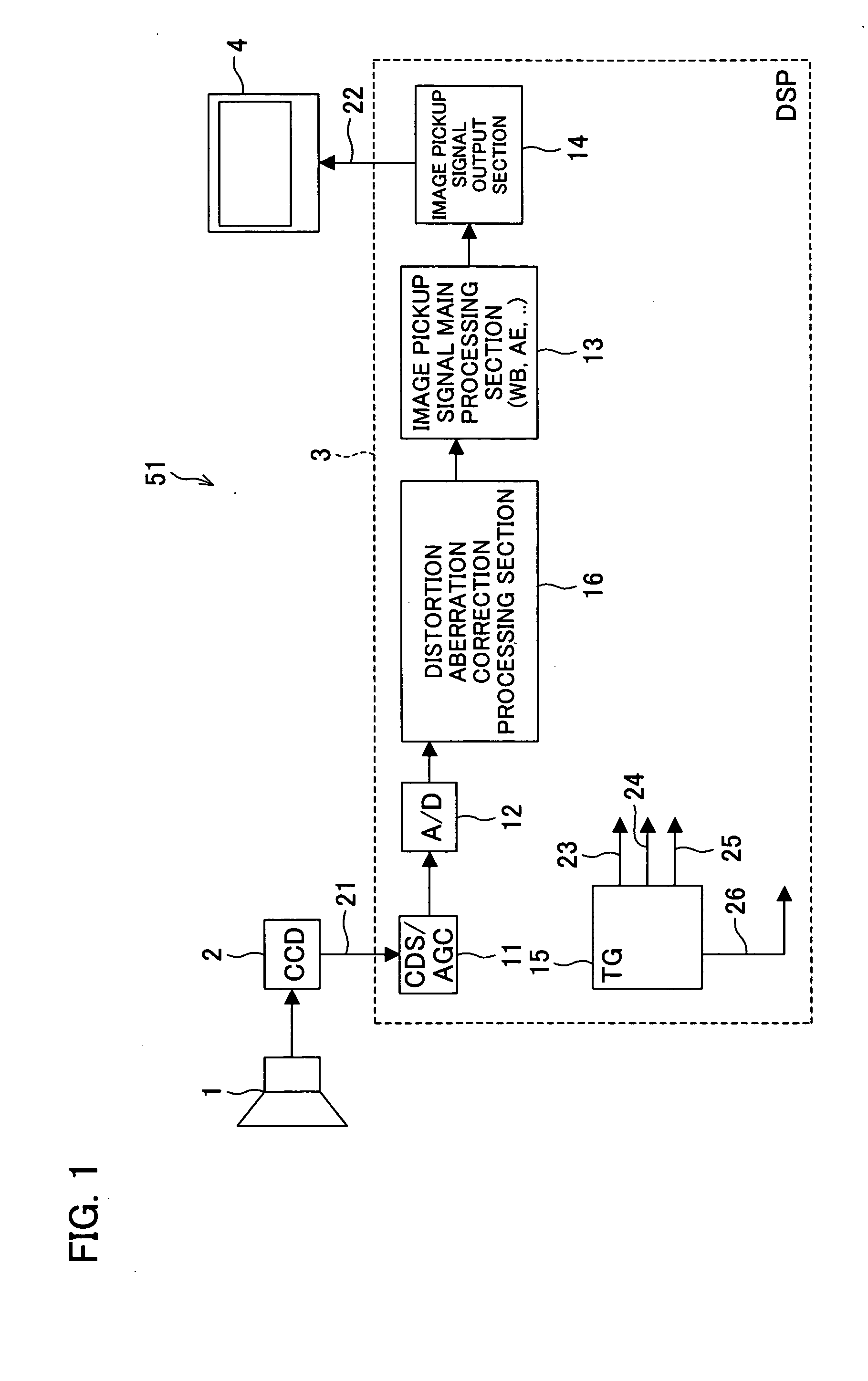
[0075]FIG. 1 shows the structure of the solid-state image pickup apparatus (image pickup apparatus) 51 in accordance with the present embodi...


PUM


Abstract

In the DSP which processes an image pickup signal obtained via an optical lens (imaging optical system) and outputs the resulting image pickup signal as processes to an image display section, distortion aberration due to the optical lens is corrected according to a distance from a pixel position corresponding to an optical axis of the optical lens by changing the pixel position for each of a target image in radial directions when the pixel position corresponding to the optical axis is set as a center while suppressing an occurrence of jaggy in the resulting image. With this structure, an image pickup apparatus which corrects distortion aberration by changing pixel position only in radial directions from a pixel position corresponding to an optical axis of the imaging optical system while suppressing an occurrence of jaggy.

Description

[0001] This non-provisional application claims priority under 35 U.S.C. § 119(a) on Patent Application No. 2004 / 12219 filed in Japan on Apr. 16, 2004, the entire contents of which are hereby incorporated by reference. FIELD OF THE INVENTION [0002] The present invention relates to an image pickup apparatus for processing image pickup signal as outputted from a solid-state image pickup element and other image processing apparatuses, which are applicable to, for example, video cameras, electron still cameras, cameras for portable telephones, and other electron cameras. BACKGROUND OF THE INVENTION [0003] In recent years, solid-state image pickup apparatuses adopting solid-state image pickup elements have been widely used for video cameras, electron still cameras, cameras for potable telephones, and other electron cameras. For such solid-state image pickup apparatuses, it is expected to improve the quality of the image picked up by the solid-state image pickup apparatus. To realize impro...

Claims


Application Information

Patent Timeline
Patent Type & Authority Applications(United States)
IPC IPC(8): G06T3/00H04N5/232H04N101/00
CPCH04N5/217H04N23/81H04N25/61E05D5/06E05D3/02E05Y2900/132
Inventor IWAI, YOSHIOKIMURA, KATSUJIYOSHIDA, TAKUJI
Owner SHARP KK
Learn More