Wide-angle optical system for solid photographic component
A wide-angle optical system, solid-state imaging element technology, applied in optics, optical elements, lenses, etc., to suppress image surface curvature, maintain size and telecentricity, and correct distortion aberrations
- Summary
- Abstract
- Description
- Claims
- Application Information
AI Technical Summary
Problems solved by technology
Method used
Image
Examples
Embodiment 1
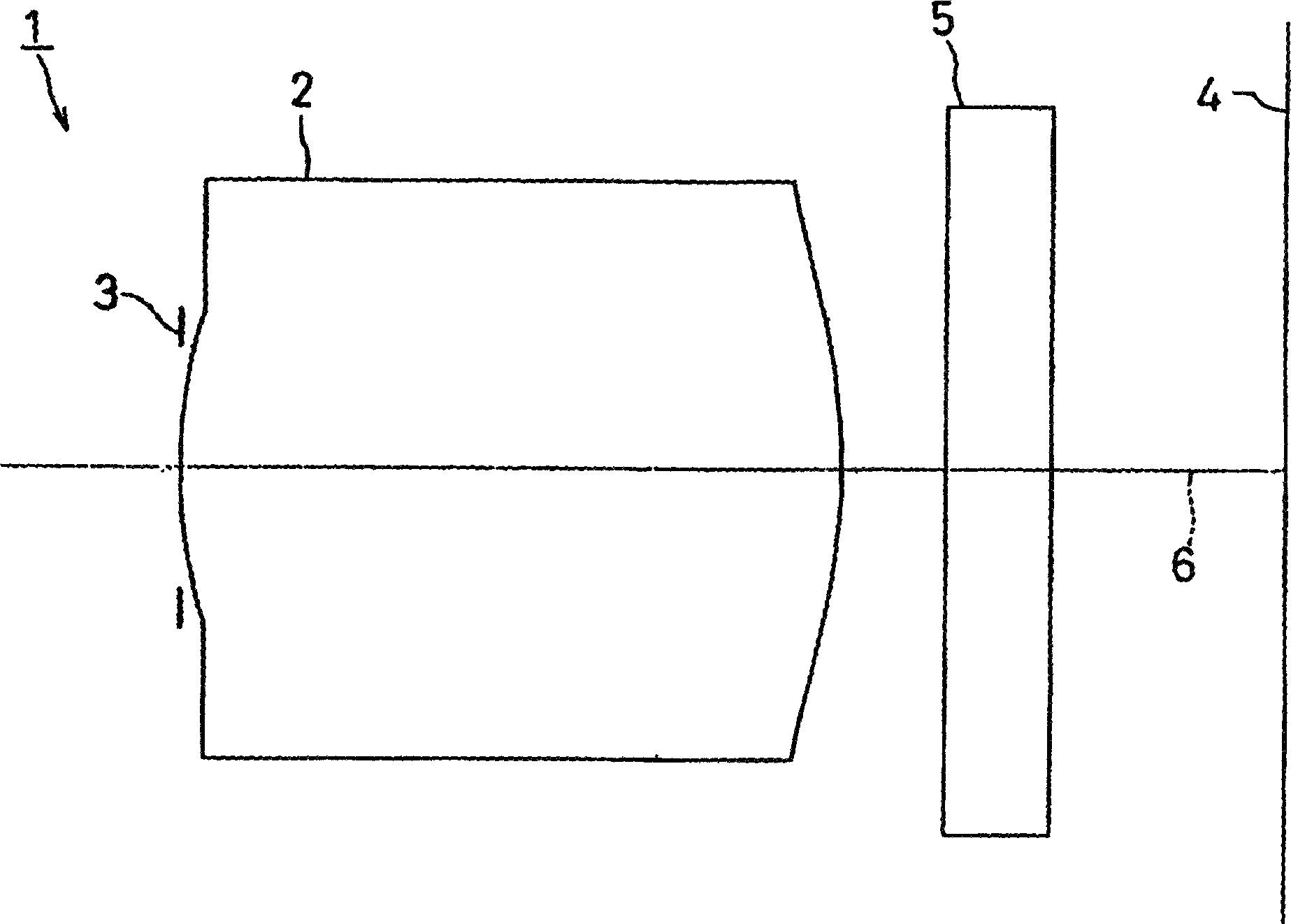
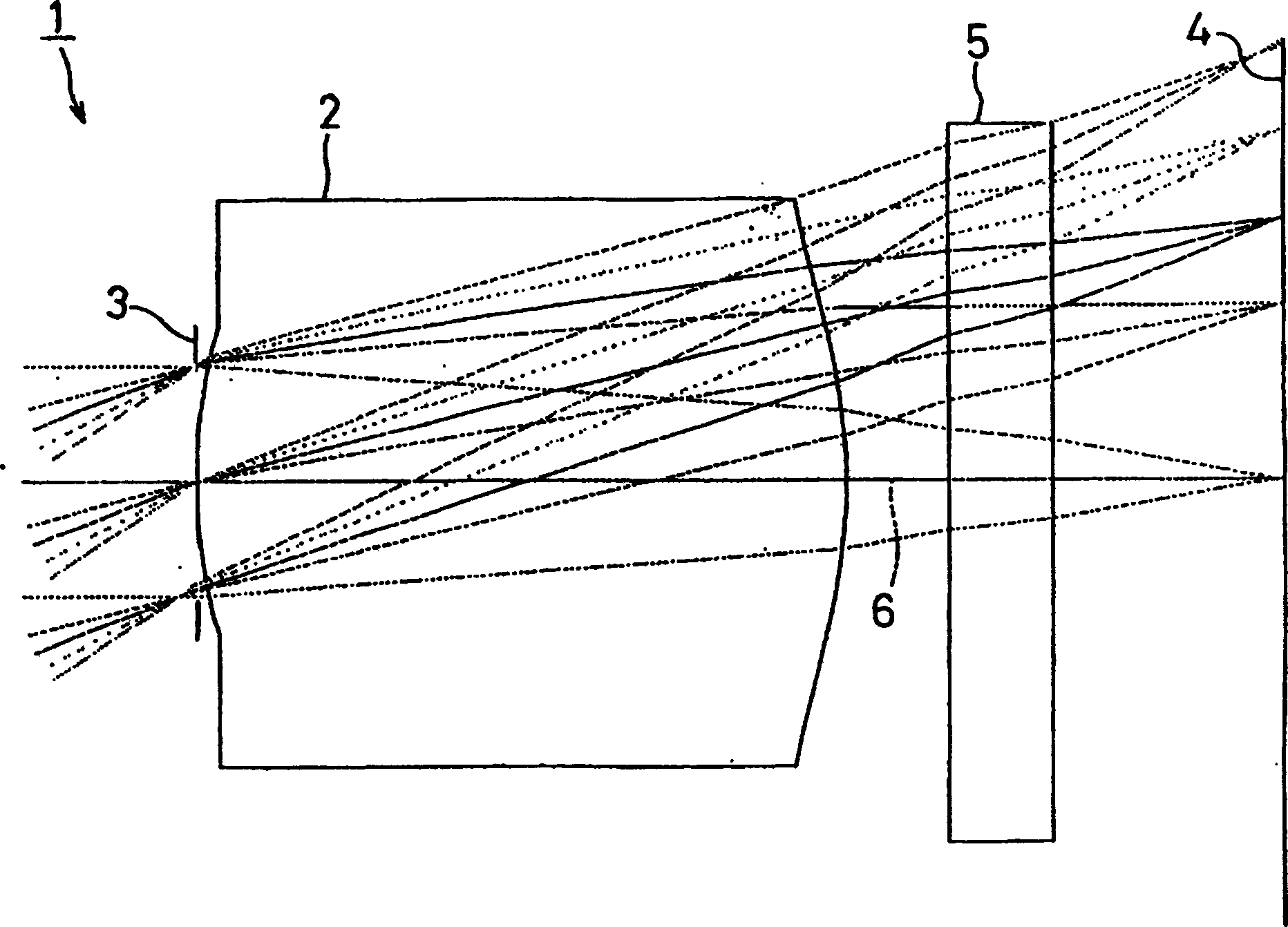
[0086] image 3 Shown is the first embodiment of the present invention, in this embodiment, with figure 1 The illustrated wide-angle optical system for solid-state imaging devices is similarly provided with an aperture 3 on the object side of the imaging lens 2 and a cover glass 5 on the imaging side.
[0087] In addition, the imaging lens 2 of the first embodiment sets the following conditions.
[0088] f1=1.50mm, FNo=2.4, 2ω=70°
[0089] i r1 d1 nd vd
[0090] 1(aperture) 0.000 0.00
[0091] 2 (first side of camera lens) 1.200 1.30 1.513 58.0
[0092] 3 (the second side of the camera lens) -1.370 0.30
[0093] 4 (1st side of cover glass) 0.000 0.70 1.518 64.0
[0094] 5 (the second side of the cover glass) 0.000 0.19
[0095] 6 (camera surface) 0.000 0.00
[0096] Aspheric coefficient
[0097] i k a b c d
[0098] 2 -2.00e-001 1.75e-001 -5.82e+000 3.59e+001 -1.00e+001
[0099] 3 -9.30e-001 2.67e-001 2.33e-003 2.76e-001 3.00e-001
[0100] Under such conditions, |r1 / ...
Embodiment 2
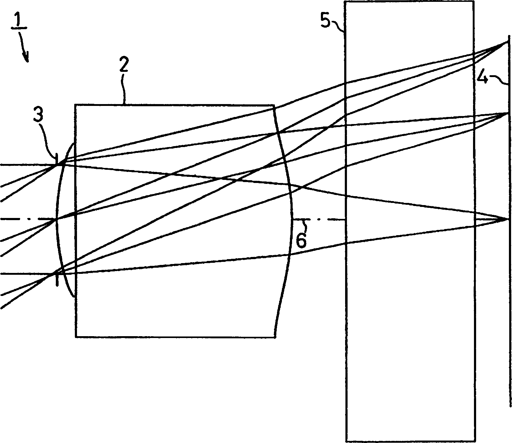
[0103] Figure 5 Shown is the second embodiment of the present invention, in this embodiment, with figure 1 The illustrated wide-angle optical system for solid-state imaging devices is similarly provided with an aperture 3 on the object side of the imaging lens 2 and a cover glass 5 on the imaging side.
[0104] In addition, the imaging lens 2 of the second embodiment sets the following conditions.
[0105] f1=1.60mm, FNo=2.8, 2ω=67°
[0106] i r1 d1 nd vd
[0107] 1(aperture) 0.000 0.00
[0108] 2 (first side of camera lens) 1.450 1.45 1.525 56.0
[0109] 3 (the second side of the camera lens) -1.325 0.30
[0110] 4 (1st side of cover glass) 0.000 0.70 1.518 64.0
[0111] 5 (the second side of the cover glass) 0.000 0.29
[0112] 6 (camera surface) 0.000 0.0000
[0113] Aspheric coefficient
[0114] i k a b c d
[0115] 2 -2.44e-000 9.00e-002 -1.80e+000 7.05e+000 -5.00e+000
[0116] 3 -2.33e+000 1.27e-001 -2.43e-001 6.51e-001 0.00e+000
[0117] Under such conditio...
Embodiment 3
[0119] Figure 7 Shown is the 3rd embodiment of the present invention, in this embodiment, with figure 1 The illustrated wide-angle optical system 1 for a solid-state imaging device is similarly provided with a diaphragm 3 on the object side of the imaging lens 2 and a cover glass 5 on the imaging side.
[0120] In addition, the following conditions are set for the imaging lens 2 in the third embodiment.
[0121] f1=2.00mm, FNo=2.8, 2ω=67°
[0122] i r1 d1 nd vd
[0123] 1(aperture) 0.000 0.00
[0124] 2 (first side of camera lens) 1.650 1.41 1.525 56.0
[0125] 3 (the second side of the camera lens) -2.060 0.30
[0126] 4 (1st side of cover glass) 0.000 0.70 1.518 64.0
[0127] 5 (the second side of the cover glass) 0.000 0.65
[0128] 6 (camera surface) 0.000 0.00
[0129] Aspheric coefficient
[0130] i k a b c d
[0131] 2 6.51e+000 2.34e-001 -8.51e+000 3.49e+001 1.00e+000
[0132] 3 -1.32e+000 1.96e-001 -2.30e-001 4.13e-001 3.88e-002
[0133] Under such condit...
PUM
 Abstract
Description
Claims
Application Information
 - R&D
- Intellectual Property
- Life Sciences
- Materials
- Tech Scout
- Unparalleled Data Quality
- Higher Quality Content
- 60% Fewer Hallucinations
Browse by: Latest US Patents, China's latest patents, Technical Efficacy Thesaurus, Application Domain, Technology Topic, Popular Technical Reports.
© 2025 PatSnap. All rights reserved.Legal|Privacy policy|Modern Slavery Act Transparency Statement|Sitemap|About US| Contact US: help@patsnap.com


