Video Endoscope and Handle, Including Driven Rotation Limitation, For Video Endoscope

a technology of endoscope and video, which is applied in the direction of optical elements, applications, instruments, etc., can solve the problems of flexible electric connection being overextended, unfavorable for the user, and bending around itself,

Active Publication Date: 2021-01-14
KARL STORZ GMBH & CO KG
View PDF4 Cites 1 Cited by
  • Summary
  • Abstract
  • Description
  • Claims
  • Application Information

AI Technical Summary

Benefits of technology

[0007]The present invention solves problems faced by the prior art with a new videoendoscopic system comprising a handle for a video endoscope, in particular for a medical or industrial video endoscope, comprising a housing and an interface portion rotatably supported relative to the housing, wherein the interface portion comprises a first connector element at its distal end section, the first connector element is connectable to a second connector element of an associated elongate shaft to form a detachable, rotatable electrical and / or mechanical connection between the handle and the associated shaft, and comprising an electrical connection assembly arranged at an exterior of the interface portion forming an electrical connection to a stationary electric and / or electronic component of the handle, wherein the first connector element is electrically connected to the electrical connection assembly, and the handle comprises a mechanical rotation stop for a rotation of the interface portion relative to the housing, such that a rotation range of the interface portion and / or the connected shaft is limited and damage to the electrical connection assembly is prevented.
[0008]Therewith, a handle for a video endo scope is provided which permits the improved handling and orientation of a video endoscope for a user with two separate systems rotatable relative to each other. The shaft may be rotated by the user during use relative to the housing of the handle without reaching the maximum rotational angle allowed by the electrical connection assembly, and therewith there is no danger of damages to the electrical connection assembly or the disconnection of the electrical connectors within the handle as a result of rotation. In addition, of course, at the choice of the operator, the handle may be rotated relative to the stationary shaft, for example for changing the hand position of the operator at a same object view, or the two may be rotated independently, relative to each other. It is particularly beneficial that a rotatable electrical and / or mechanical connection between the shaft and the handle is provided which limits to the rotation of the interface portion and therewith, a connected shaft, to avoid damage to the electrical connection and / or the electrical connection assembly, but still provides operational benefits, such as the ability to maintain a constant orientation of the outer housing of the handle and therefore a constant orientation of the operator controls and keys located on the handle for the user. During an endoscopic operation, the user is generally accustomed to change the direction of rotation of the shaft at any moment during navigation and viewing inside a body cavity, and therefore, the mechanical rotation stop to limit rotation of the interface portion and therewith the connected shaft, improves the electrical reliability of the handle and shaft, and therefore video endoscope is enhanced, permitting the prolongation of an endoscopic procedure and reducing the risk involved in a medical endoscopic intervention.
[0009]Thus, an efficient, user-friendly, and electrically reliable handle for a video endoscope is provided to house the image sensor in the distal end of the shaft of the video endoscope in a manner similar to traditional endoscopes wherein a proximal image sensor is housed within a camera head attached to the endoscopic shaft, while enabling an electrical, rather than optical image transmission, from the connected shaft to the handle and, in particular, further to a processing unit.

Problems solved by technology

Furthermore during an endoscopic procedure, the user is frequently required to change a rotational orientation of the endoscope in order to vary the view of the object field, and in with the limitations of conventional video endoscopes, the complete video endoscope must be rotated during examination of the cavity.
As such, the operator controls, buttons or touch keys, which are usually arranged at the top side of the handle in its upright position, are arranged in an unfavorable position for the user during rotation.
This design is especially disadvantageous, because normally the handle is held by the same hand of the user that likewise operates the operator buttons or touch keys.
Nevertheless, still, the problem remains that this flexible electric connection may twist around itself, be over extended, or even be damaged and may tear off during rotation of the shaft relatively to the outer housing while using the video endoscope.
However, EP 3 197 146 A1 does not address the rotation of a shaft of a video endoscope and a rotatable, couplable electric connection.

Method used


Image

  • Video Endoscope and Handle, Including Driven Rotation Limitation, For Video Endoscope
  • Video Endoscope and Handle, Including Driven Rotation Limitation, For Video Endoscope
  • Video Endoscope and Handle, Including Driven Rotation Limitation, For Video Endoscope

Examples


Embodiment Construction

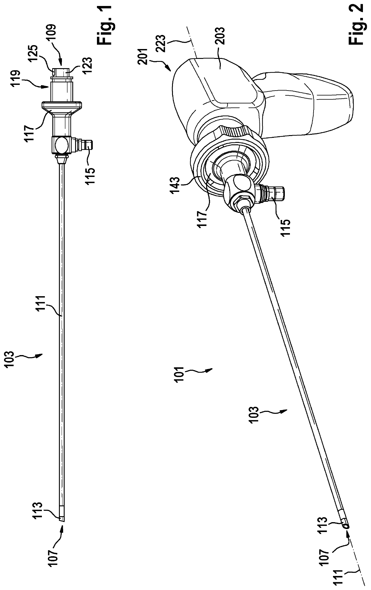
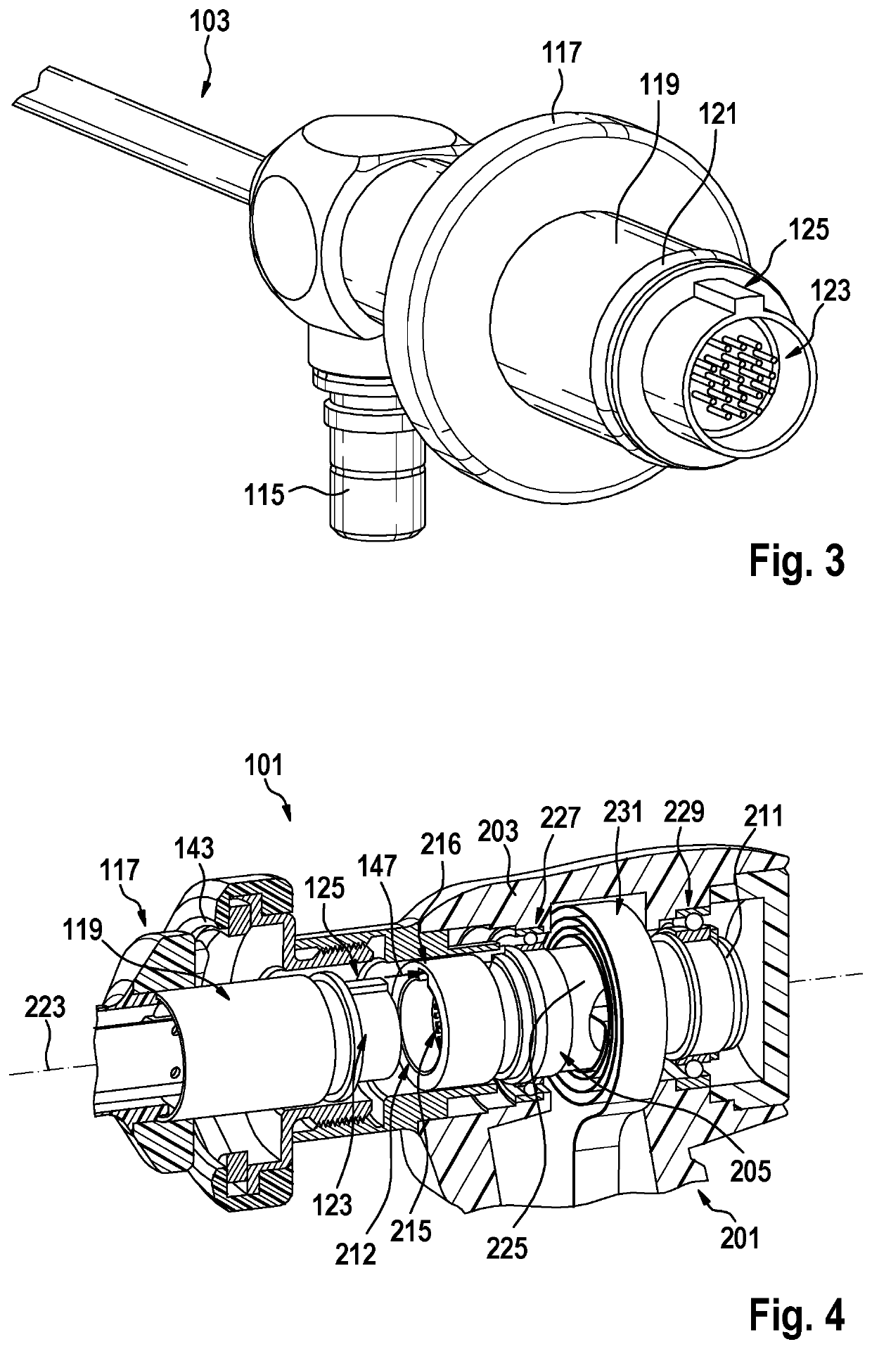
[0089]A video endoscope 101 comprises a shaft 103 and a handle 201 (see FIG. 2). The shaft 103 comprises at its distal end 107 two image sensors 113. Furthermore, the shaft 103 comprises a longitudinal axis 111 between its distal end 107 and its proximal end 109. At its proximal end 109, the shaft 103 comprises a second connector element 119 with a 21-pin plug 123. The 21-pin plug 123 has a pin 125 at its top side (see FIG. 3). The 21-pin plug 123 is arranged hermetically sealed to the second connector element 119. Furthermore, the second connector element 119 comprises an O-ring seal 121 around its outer peripheral surface for sealing a connection with a first connector element 213. Furthermore, the shaft 103 comprises an eyepiece cup 117 and a light post 115 for connecting a light source.

[0090]In a connected state, the shaft 103 and the handle 201 form the video endoscope 101. Hereby, the eyepiece cup 117 of the shaft 103 is an additionally, mechanically connected via a claw coupl...


PUM


Abstract

The invention concerns a handle for a video endoscope including a housing and an interface portion rotatably supported relative to the housing where the interface portion includes a first connector element at its distal end section that is connectable to a second connector element of an associated elongate shaft of the video endoscope. Thereby a detachable, rotatable electrical and / or mechanical connection between the handle and the associated shaft is achieved. The coupling includes an electrical connection assembly arranged at an exterior of the interface portion forming an electrical connection to a stationary electric component of the handle. The handle includes a mechanical rotation stop for a rotation of the interface portion relative to the housing such that a rotation range is limited and damage to the electrical connection assembly is prevented.

Description

CROSS REFERENCE TO RELATED APPLICATIONS[0001]This application claims priority to German Patent Application No. 102019004433.9, filed Jun. 22, 2019, and entitled, “Video endoscope and handle for a video endoscope,” and is incorporated herein by reference.FIELD OF THE INVENTION[0002]The invention relates to a handle for a video endoscope, in particular for a medical or industrial video endoscope.BACKGROUND OF THE INVENTION[0003]For medical or non-medical applications, endoscopes comprise an elongate shaft configured for being introduced into an internal cavity of a human or animal body or another object for examination. For generating an image of an object field in the cavity, an imaging optic is located in a distal (meaning distant from a user) end section of the shaft. On the opposite, proximal (meaning close to the user) end section of the shaft, a handle is attached for operating the endoscope by the user. In case of video endoscopes, which are also known as electronic endoscopes,...

Claims


Application Information

Patent Timeline
Patent Type & Authority Applications(United States)
IPC IPC(8): A61B1/00A61B1/05A61B1/06
CPCA61B1/00124A61B1/00066A61B1/0669A61B1/0684A61B1/053A61B1/05A61B1/00128A61B1/00073G02B23/2476G02B23/2461A61B1/00042A61B90/03A61B2090/035A61B1/00018A61B1/00027A61B1/0661G02B23/2484H01R39/643H01R2201/12A61B1/00009H04N23/54H04N23/555
Inventor HENI, PASCALKUPFERSCHMID, MARKUSFORSTER, JONAS
Owner KARL STORZ GMBH & CO KG
Why Eureka
Try Eureka