
Valve

Active Publication Date: 2021-01-28
FESTO AG & CO KG
View PDF0 Cites 1 Cited by
  • Summary
  • Abstract
  • Description
  • Claims
  • Application Information

AI Technical Summary

Benefits of technology

The aim of this invention is to ensure the valve operates reliably and with minimal wear and tear.

Problems solved by technology

In particular, this prevents the valve slide which is normally surrounded by rubber-elastic sealing rings being pushed unevenly by the compression spring onto the sealing rings, which could result in leaks and localised signs of wear.

Method used


Image

  • Valve
  • Valve
  • Valve

Examples


Embodiment Construction

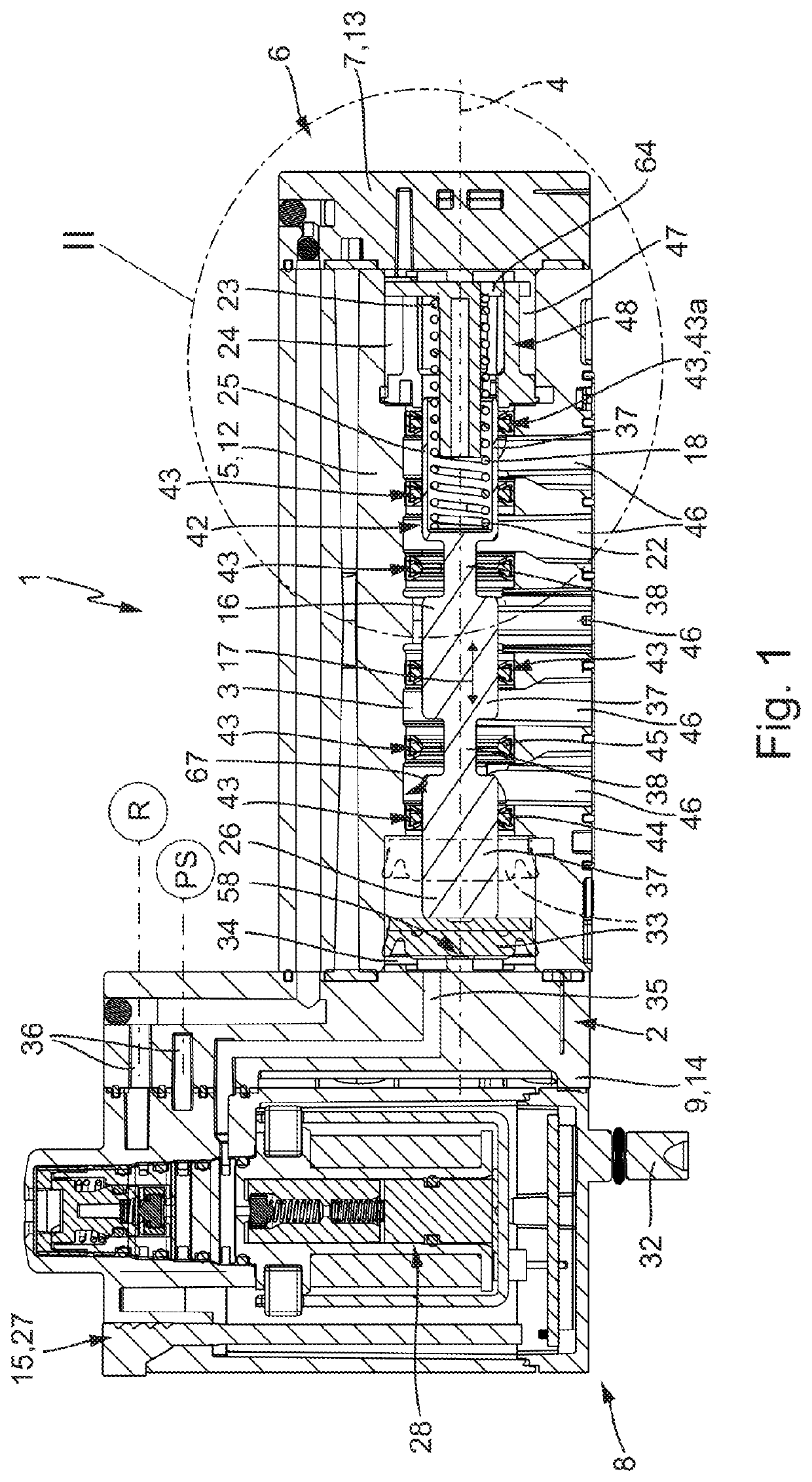
[0035]The valve designated in its entirety by reference numeral 1 serves to control the flow of a fluidic pressure medium, which in particular involves compressed air.

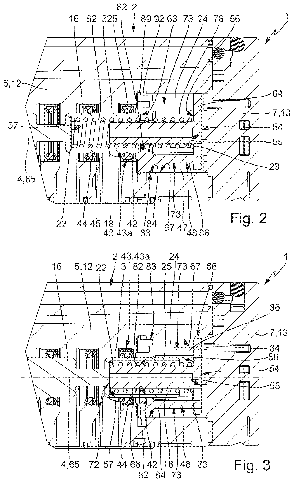
[0036]The valve 1 has a valve housing 2, in which a housing interior 3 having a longitudinal extension is formed. The housing interior 3 has a main axis 4 shown in a dot-dash fashion, which is formed by the central longitudinal axis of the housing interior 3.

[0037]The valve housing 2 has a housing perimeter wall 5 delimiting the housing interior at its radial outer circumference. It also has a housing rear wall 7 sealing the housing interior 3 on a rear side 6 of the valve 1. On a front side 8 the housing interior 3 is delimited by a housing front wall 9.

[0038]The valve housing 2 has a multi-part design and has a housing main body 12 forming the housing perimeter wall 5. The housing rear wall 7 is preferably formed by a housing cover 13 that is separate from the housing main body 12, which for a better differentiation ...


PUM


Abstract

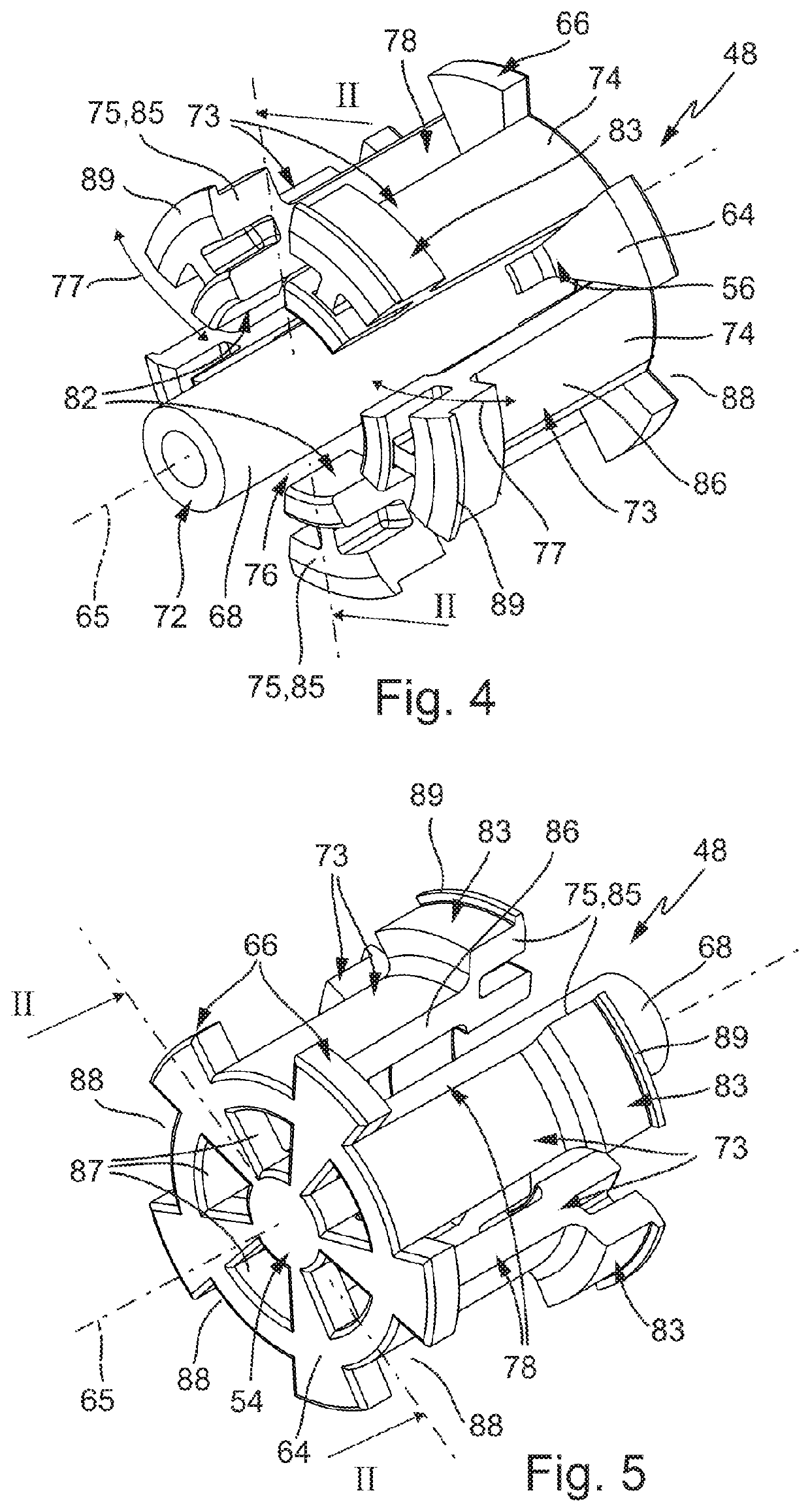
A valve, having a valve housing, in which a housing interior is formed, in which a movable valve slide is located. The valve slide is impinged upon by a compression spring that is supported via a supporting element on the valve housing. The supporting element has a supporting wall, from which a plurality of supporting arms protrudes, which axially overlap the valve slide in each axial position. On the supporting arms guide surfaces are formed for linear guidance of the valve slide. The supporting arms are springily deflectable and in each case have a radial support surface, with which they are supported on the valve housing.

Description

BACKGROUND OF THE INVENTION[0001]The invention relates to a valve, with a valve housing, in which a housing interior extending along a main axis is formed and which has a housing perimeter wall delimiting the housing interior at its radial outer circumference and a housing rear wall delimiting the housing interior at a rear side, with a valve slide arranged in the housing interior, which is axially displaceable for positioning in various switching positions relative to the valve housing by changing its axial position adopted in relation to the valve housing, and with a compression spring arranged in the housing interior in a rear interior end portion axially between the valve slide and the housing rear wall, by which the valve slide is preloaded in one of its possible switching positions and which is supported on the one hand on a rear end portion of the valve slide facing the housing rear wall and on the other hand on a supporting wall of a supporting element extending in the rear ...

Claims


Application Information

Patent Timeline
IPC IPC(8): F15B13/04F16K11/07
CPCF15B13/0402F16K27/041F16K11/0712F16K11/0716F16K17/10F15B13/0431F16K31/426F16K11/07F15B2211/322
Inventor KAYABAS, METIN
Owner FESTO AG & CO KG
Learn More