Cooling Apparatus for a Motor Vehicle, and Motor Vehicle Having Such a Cooling Apparatus

Active Publication Date: 2019-07-25
BAYERISCHE MOTOREN WERKE AG
View PDF0 Cites 0 Cited by
  • Summary
  • Abstract
  • Description
  • Claims
  • Application Information

AI Technical Summary

Benefits of technology

[0021]In order to realize particularly efficient operation, furthermore, it has been shown to be advantageous if the combining point coincides with the connecting point. In other words, the combining point corresponds to the connecting point or vice versa, with the result that the combining point is the connecting point or vice versa. As a result, unfavorable flows, in particular eddies, of the refrigerant which flows through the refrigerant circuit can be avoided, as a result of which particularly efficient and/or low loss operation of the cooling device is realized.
[0022]It has been shown to be particularly advantageous if the main line has an internal diameter, through which the refrigerant, in particular, flows, which internal diameter lies in a range from 14 millimeters inclusive to 20 millimeters inclusiv

Problems solved by technology

This results in efficiency disadvantages in the case of conventional cooling devices, since the pressure losses have to be compensated for at least partially via a higher actuation of the refrigerant compressor.
It is a further disadvantage that an impairment of comfort can occur, in particular in the interior compartment of the motor vehicle, in particular in the case of a full actuation of the refrigerant compressor.
The pressure losses namely lead to a rise in the evaporation temperature.
This in turn results in acoustic disadvantages and draft phenomena for occupants in the interior compartment.
A further disadvantage is, for example, the impairment of a thermal transfer to a component which is to be temperature controlled, in particular is to be climate controlled, by means of one of the evaporators, such as an energy store, in particular in the case of a f

Method used


Image

  • Cooling Apparatus for a Motor Vehicle, and Motor Vehicle Having Such a Cooling Apparatus
  • Cooling Apparatus for a Motor Vehicle, and Motor Vehicle Having Such a Cooling Apparatus

Examples


Example

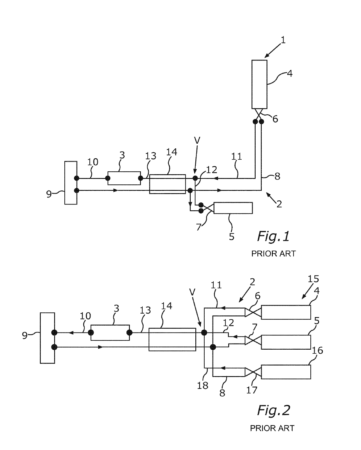
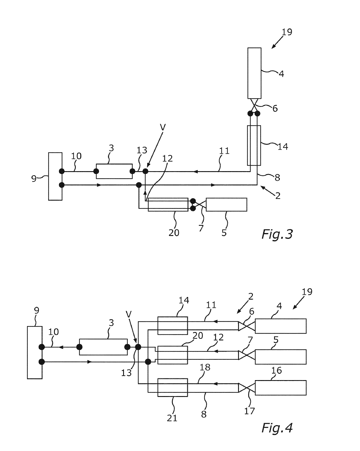
[0051]FIG. 3 shows a first embodiment of a cooling device 19, by means of which the efficiency disadvantages which were described above in conjunction with the cooling devices 1 and 15 can be avoided. It can be seen from a combined view of FIGS. 1 and 3 that the cooling device 19 proceeds from the cooling device 1 or its construction. In the case of the cooling device 19, the heat exchanger 14 is arranged as a first heat exchanger in the suction line 11 and in the feed line 8. Furthermore, the cooling device 19 comprises a second heat exchanger 20 which is different, for example, than the first heat exchanger 14, is provided in addition to the latter, and is arranged in the suction line 12 which is separated at least partially from the suction line 11 and in the feed line 8. In the flow direction of the refrigerant which flows through the respective suction line 11 and 12, the respective heat exchanger 14 and 20, respectively, is arranged in the respective suction line 11 and 12, re...

Example

[0052]FIG. 4 shows a second embodiment of the cooling device 19, the second embodiment of the cooling device 19 being based on the cooling device 15 or proceeding therefrom. The second embodiment comprises a third heat exchanger 21 which is different than the heat exchangers 14 and 20 and is provided in addition to the latter, the heat exchangers 14, 20 and 21 being configured as internal or inner heat exchangers. The third heat exchanger 21 is arranged both in the third suction line 18 and in the feed line 8, and therefore refrigerant which flows toward the evaporator 16 and flows away from the evaporator 16 and flows to the refrigerant compressor 3 flows through said third heat exchanger 21. In a corresponding manner to this, refrigerant which flows toward the evaporator 5 and refrigerant which flows from or away from the evaporator 5 and in the process flows to the refrigerant compressor 3 flows through the heat exchanger 20. In a corresponding manner to this, refrigerant which f...

Example

[0053]In a further, third embodiment (not shown in the figures), it can be provided that, for example, the third heat exchanger 21 is omitted, the second heat exchanger 20 then being a heat exchanger which is common to the evaporators 5 and 16 and, for example, is arranged both in the suction line 12 and in the suction line 18 and in the feed line 8. In other words, if the number of evaporators is x, for example, x-1 evaporators are assigned, for example, to a common inner heat exchanger, the remaining evaporator being equipped with a dedicated internal heat exchanger. Furthermore, it is contemplated to dispense entirely with an inner heat exchanger in at least one part section.

LIST OF DESIGNATIONS

[0054]1 Cooling device[0055]2 Refrigerant circuit[0056]3 Refrigerant compressor[0057]4 Evaporator[0058]5 Evaporator[0059]6 Expansion valve[0060]7 Expansion valve[0061]8 Feed line[0062]9 Condenser[0063]10 Line[0064]11 Suction line[0065]12 Suction line[0066]13 Main line[0067]14 Heat exchange...


PUM


Abstract

A cooling apparatus for a motor vehicle includes a coolant circuit through which a coolant can flow, a coolant compressor, a first evaporator, at least one second evaporator, a first suction line for leading the coolant from the first evaporator to the coolant compressor, a second suction line, a main line connected fluidically to suction lines at a connecting point, and at least one internal heat exchanger, through which coolant flowing from the at least one of the evaporators to the coolant compressor can flow. The internal heat exchanger is arranged in at least one of the suction lines and the connecting point is arranged downstream of the at least one heat exchanger.

Description

CROSS REFERENCE TO RELATED APPLICATIONS[0001]This application is a continuation of PCT International Application No. PCT / EP2017 / 076020, filed Oct. 12, 2017, which claims priority under 35 U.S.C. § 119 from German Patent Application No. 10 2016 220 474.2, filed Oct. 19, 2016, the entire disclosures of which are herein expressly incorporated by reference.BACKGROUND AND SUMMARY OF THE INVENTION[0002]The invention relates to a cooling device for a motor vehicle and to a motor vehicle, in particular a car, having such a cooling device.[0003]Cooling devices for motor vehicles, in particular for cars, are already well known from the general prior art and, in particular, from series vehicle production. The cooling device has a refrigerant circuit, through which a refrigerant can flow. Furthermore, the cooling device has a refrigerant compressor which is arranged in the refrigerant circuit and by which the refrigerant is to be compressed or can be compressed. Furthermore, the cooling device ...

Claims


Application Information

Patent Timeline
IPC IPC(8): B60H1/00B60H1/32
CPCB60H1/00278B60H1/323B60H2001/00307F01P2060/08
Inventor ALLGAEUER, CHRISTIANHORN, OLIVERKNOTT, MARTIN
Owner BAYERISCHE MOTOREN WERKE AG
Why Eureka
Try Eureka