Current mirror with low static current and transconductance amplifier thereof

Inactive Publication Date: 2006-06-15
IND TECH RES INST
View PDF8 Cites 6 Cited by
  • Summary
  • Abstract
  • Description
  • Claims
  • Application Information

AI Technical Summary

Benefits of technology

[0010] In view of the foregoing, the invention provides a current mirror with a low static current and uses it in a transconductance amplifier.
[0011] An objective of the invention is to provide a current mirror with a low static current to operate under a low voltage supply.
[0012] Another objective of the invention is to provide a transconductance amplifier with a low static current and high slew rate. It can operate under a low voltage supply or under different bias currents.
[0013] The disclosed current mirror with a low static current contains: a load with a first end and a second end, the first end coupling to a first input current and a fixed voltage difference existing between the first end and the second end; a first transistor, whose drain is coupled to the second end of the load, whose gate

Problems solved by technology

This current mirror is limited by small signal space and low output impedance.
This current mirror can increase the output impedance, but still suffers from the restriction of small signal space.
However, it needs a continuous supply of the bias current Ibias, renderin

Method used


Image

  • Current mirror with low static current and transconductance amplifier thereof
  • Current mirror with low static current and transconductance amplifier thereof
  • Current mirror with low static current and transconductance amplifier thereof

Examples


Example

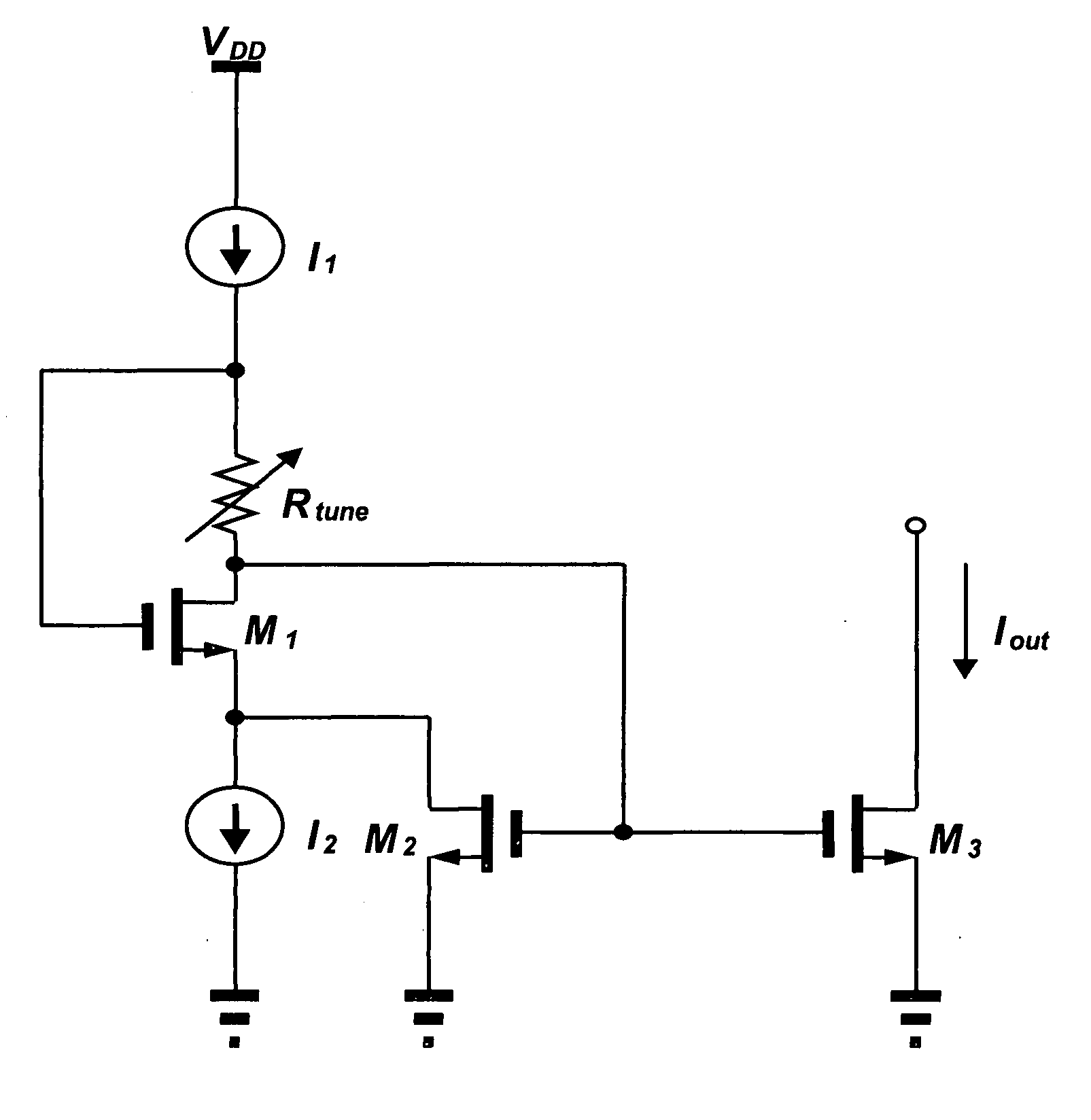
[0025]FIG. 6 shows the current mirror with a low static current according to a first embodiment of the invention. The load is a tunable resistor Rtune. The current mirror 30 with a low static current contains a tunable resistor Rtune, a first transistor M1, a second transistor M2, and a third transistor M3.

[0026] The tunable resistor Rtune has a first end and a second end. The first end is coupled to the first input current I1. A fixed voltage difference VDS is supplied between the first and second ends.

[0027] The tunable resistor Rtune can be made of a metal oxide semiconductor (MOS) operating in the semiconductor linear region.

[0028] The drain of the first transistor M1 is coupled to the second end of the tunable resistor Rtune. Its gate is coupled to the first end of the tunable resistor Rtune. Its source is coupled to the second input current I2.

[0029] The drain of the second transistor M2 is coupled to the source of the first transistor M1. Its gate is coupled to the second...

Example

[0034]FIG. 7 shows a second embodiment of the disclosed current mirror with a low static current. In this embodiment, the load is a combination of an amplifier Amp and a fourth transistor M4.

[0035] The current mirror 30 with a low static current includes: a first transistor M1, a second transistor M2, a third transistor M3, a fourth transistor M4, and an amplifier Amp.

[0036] The amplifier Amp includes a positive input end, a negative input end, and an output end.

[0037] The drain of the fourth transistor M4 is coupled to the positive input end of the amplifier Amp. Its gate is coupled to the output end of the amplifier Amp. Its source is coupled to the negative input end of the amplifier Amp.

[0038] The drain of the fourth transistor M4 is a first end of the load. Its source is a second end of the load. When the current passing through the fourth transistor M4 changes, a negative feedback mechanism is formed through the connection of the amplifier Amp, adjusting the voltage drop b...

Example

[0045]FIG. 9 shows a block diagram of the transconductance amplifier in a third embodiment of the invention. The transconductance amplifier contains: a voltage amplifier stage 30, a transconductance stage 40, and a current amplifier stage 50.

[0046] The voltage amplifier stage 30 amplifies the voltage. The transconductance stage 40 is coupled to the voltage amplifier stage 30 to convert the voltage into a current. The current amplifier stage 50 is coupled to the transconductance stage to amplify the current. It contains a current mirror with a low static current that is used as a reference buffer at a low voltage or as a current driver.

[0047]FIG. 10 shows the circuit diagram of the transconductance amplifier in the third embodiment. The voltage amplifier stage 30 contains: a first voltage amplifier 10 and a second voltage amplifier 20 coupled with each other.

[0048] The first voltage amplifier 10 contains: a first input differential pair and a first load differential pair. The tran...


PUM


Abstract

A current mirror with a transconductance amplifier containing the current mirror with a low static current. The current mirror includes: a load with first end and a second end, the first end coupling to a first input current and a fixed voltage difference existing between the first and second ends; a first transistor, whose drain is coupled to the second end of the load, whose gate is coupled to the first end of the load, and whose source is coupled to a second input current; and a second transistor, whose drain is coupled to a third port and an output current, whose gate is coupled to the second end of the load, and whose source is coupled to the ground. The transconductance amplifier contains: a voltage amplifier stage, a transconductance stage, and a current amplifier stage for amplifying the current and containing the current mirror.

Description

BACKGROUND OF THE INVENTION [0001] 1. Field of Invention [0002] The invention relates to a current mirror and a transconductance amplifier containing the current mirror. In particular, the invention relates to a current mirror with a low static current and a transconductance amplifier containing the current mirror with a low static current. [0003] 2. Related Art [0004] The current mirror is a basic and important analog device, widely used in bias circuits and the loads in an amplifier stage. [0005] As shown in FIG. 1, a conventional current mirror has a first transistor M1 and a second transistor M2. The drain of M1 is coupled to its gate, and its source is coupled to the ground. The gate of M2 is coupled to the gate of M1, and its source is coupled to the ground. The first transistor M1 receives an input current Iin via the drain and generates a bias at the gate. The second transistor M2 generates an output current Iout at the drain. This current mirror is limited by small signal s...

Claims


Application Information

Patent Timeline
IPC IPC(8): H03F3/04
CPCG05F3/262H03F3/45273H03F3/45475H03F2203/45096H03F2203/45288H03F2203/45521
Inventor LOU, CHIH-HONGLIU, CHIA-CHUN
Owner IND TECH RES INST
Why Eureka
Try Eureka