Picking and supplying circuit for discharging direct current

Inactive Publication Date: 2006-01-17
HUEI LIN MIN
View PDF3 Cites 1 Cited by
  • Summary
  • Abstract
  • Description
  • Claims
  • Application Information

AI Technical Summary

Benefits of technology

[0004]Therefore, the purpose of the present invention is to provide a kind of Picking and Supplying Circuit for Discharging Direct Current, which consumes a low current and disc

Problems solved by technology

Thus, based on the general techniques the former patent indicates, it will consume a lot of alternating current before discharging direct current resulting in negative electric loadi

Method used


Image

  • Picking and supplying circuit for discharging direct current
  • Picking and supplying circuit for discharging direct current
  • Picking and supplying circuit for discharging direct current

Examples


Embodiment Construction

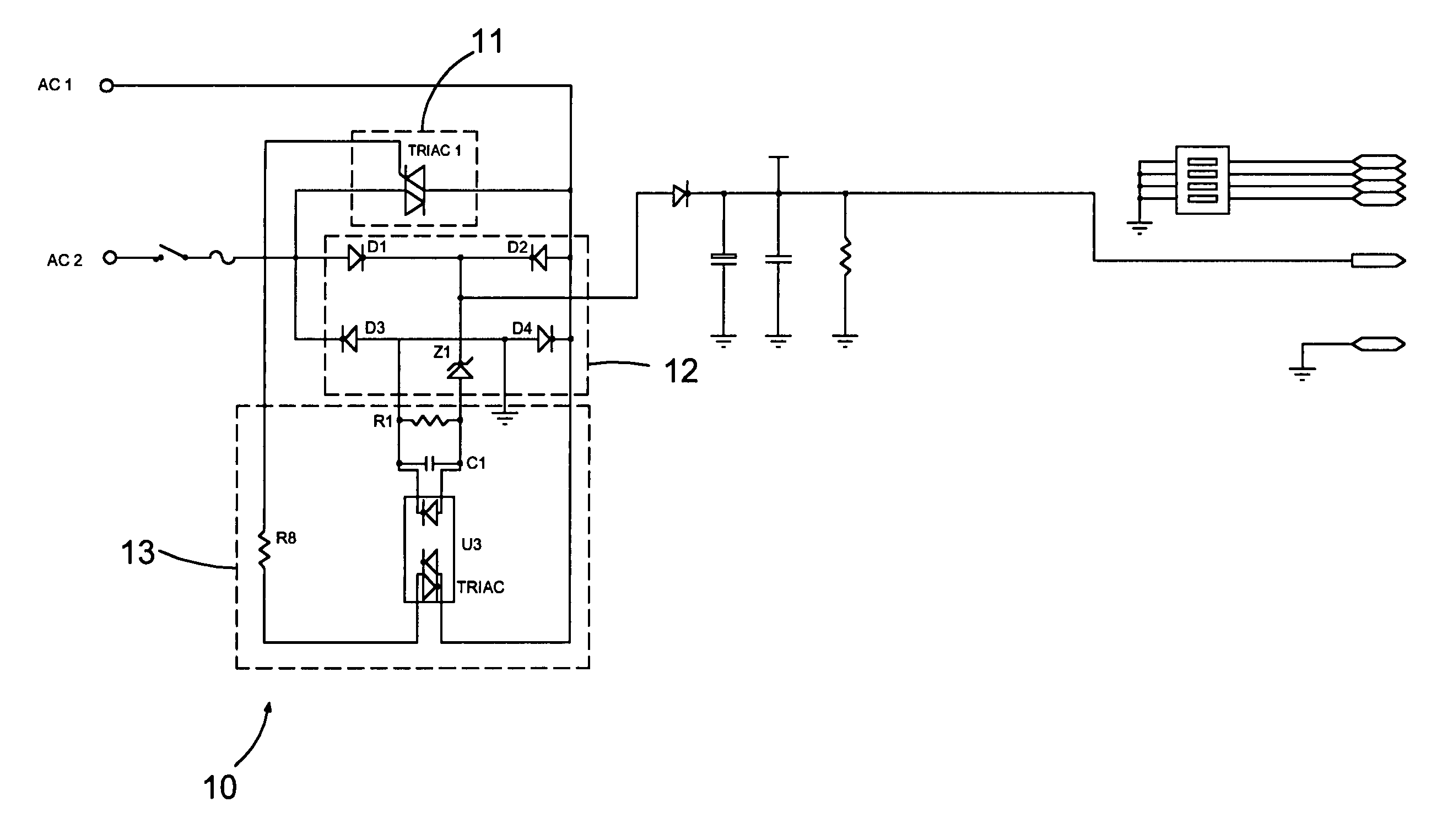
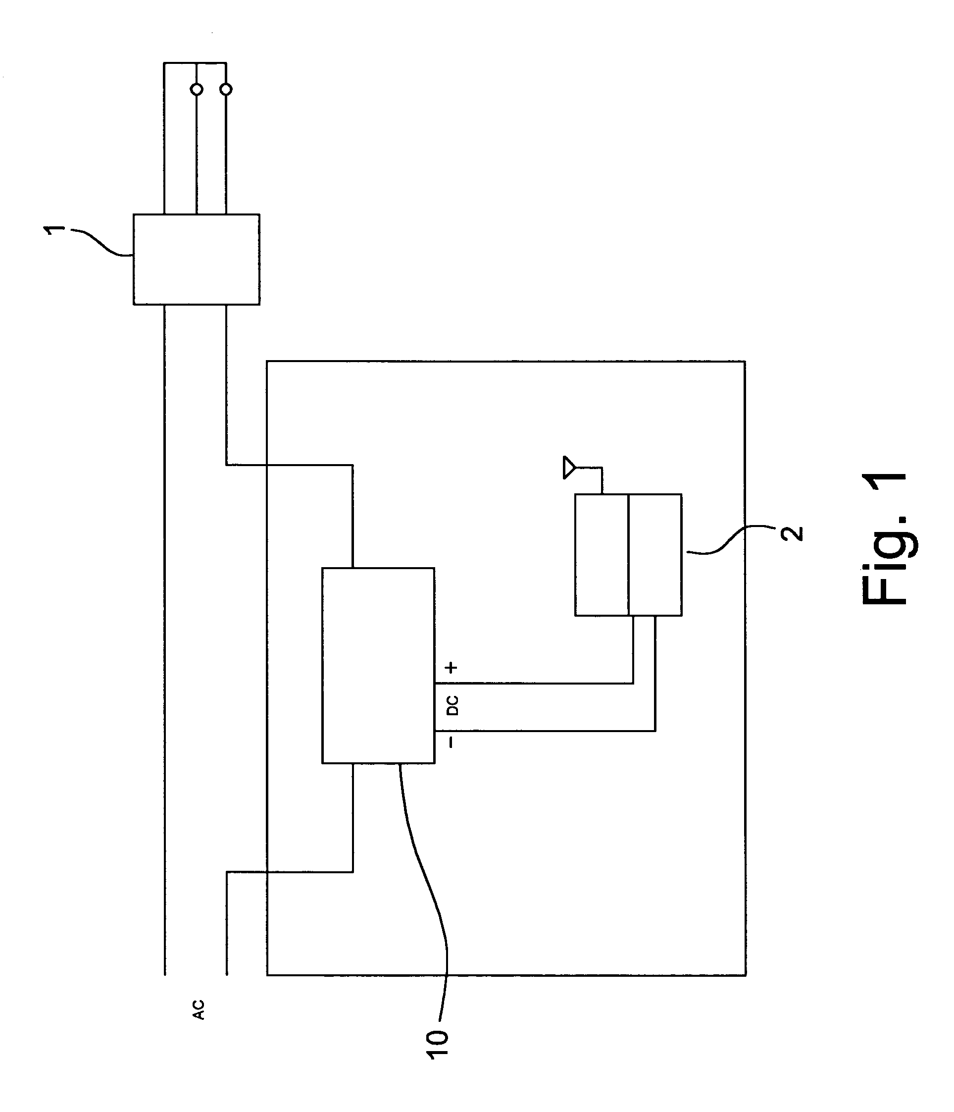
[0010]As shown in all figures, the present invention provides a kind of Picking and Supplying Circuit for Discharging Direct Current (10), which is meeting the demand of telecontrol wall controller (2) for discharging and supplying direct current for electrical loading (1). It is connected with supplying line of alternating current of electrical loading in series for picking alternating current of low volume for driving the telecontrol wall controller (2).

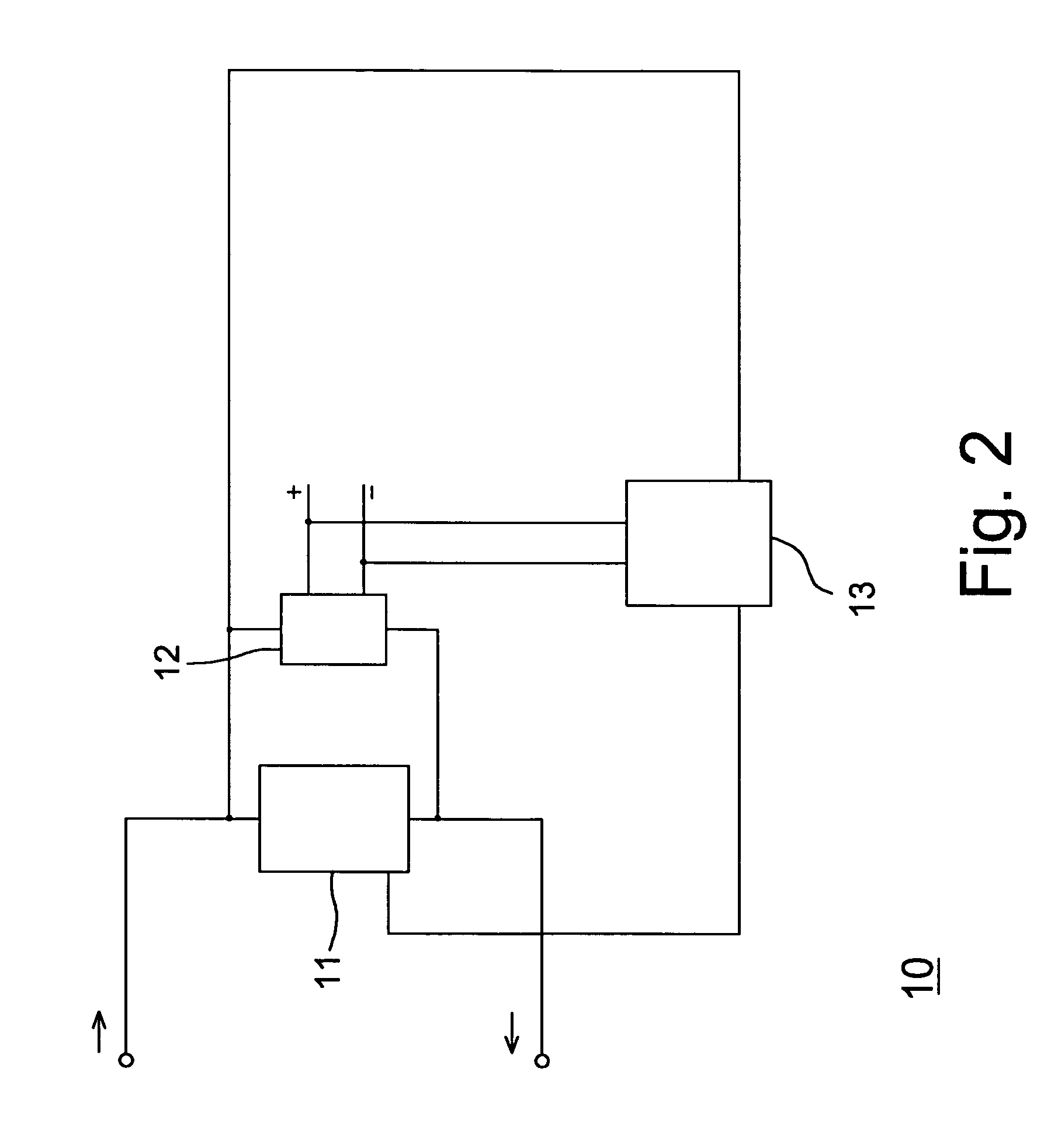
[0011]This Picking and Supplying Circuit for Discharging Direct Current (10) is composed of a picking part (11), a commutation and voltage regulating loop (12) and a trigger loop (13).

[0012]The picking part (11) takes the trielectrode AC switch (TRIAC1) as its control triac, and is connected with the supplying circuitry of alternating current for electrical loading with lines.

[0013]The commutation and voltage regulating loop (12), which has two pairs of diodes ((D1 and D2) and (D3 and D4)) connected reversely in series each other, ...


PUM


Abstract

The present invention provides a kind of Picking and Supplying Circuit for Discharging Direct Current, which is connected with supplying line of alternating current of electrical loading in series. It contains a picking part with a control triac under a closing state, for picking the alternating current of specified volume; a commutation and voltage regulating loop, which has two pairs of diodes connected reversely in series each other, and one diode with certain voltage is connected between a pair of diodes connected in series for commutating the picked alternating current and regulating voltage and discharging the direct current; a trigger loop was designed for connecting commutation and voltage regulating loop and providing a reverse sign to make the control triac convert into an unobstructed state from the closing one and making the alternating current reply and recover the supply of the electrical loading.

Description

FIELD OF THE PRESENT INVENTION[0001]The present invention provides a kind of Picking and Supplying Circuit for Discharging Direct Current, relating to wall controller of electrical appliance.BACKGROUND OF THE INVENTION[0002]Based on some investigation, the case of U.S. Pat. No. 5,898,584 patent for invention indicates the techniques for a kind of Circuit supplying power to ceiling fan. Before this patent, it was composed of cathode half-loop, anode half-loop, control loop and protective loop etc. four units for discharging direct current of proper intensity by picking proper alternating current via the cathode and anode half-loop. However for the limitation from the design of half-loops, for the loading of different intensities, a low loading control loop and a high loading control loop is designed respectively to control the control loop, so that the stable and reliable output of direct current. Although the NMOS in the control loop has an advantage in fast response, it would run a...

Claims


Application Information

Patent Timeline
IPC IPC(8): H02M7/00
CPCH02M7/00
Inventor HUEI, LIN MIN
Owner HUEI LIN MIN
Why Eureka
Try Eureka