Dial device and imaging apparatus

a dial device and dial technology, applied in the direction of mechanical control devices, camera body details, instruments, etc., can solve the problems of difficult and expensive manufacture, and achieve the effect of suppressing the rattling of the dial and generating a favorable click feeling

Active Publication Date: 2021-01-28
PANASONIC INTELLECTUAL PROPERTY MANAGEMENT CO LTD
View PDF0 Cites 0 Cited by
  • Summary
  • Abstract
  • Description
  • Claims
  • Application Information

AI Technical Summary

Benefits of technology

[0008]According to the present disclosure, in a dial device that is used in an imaging apparatus or the like and generates a click feeling, it is possible to generate a favorable click feeling by suppressing rattling of the dial.

Problems solved by technology

However, this is very difficult and expensive to manufacture, considering variations within the manufacturing tolerances of the ball and ball holding hole.

Method used


Image

  • Dial device and imaging apparatus
  • Dial device and imaging apparatus
  • Dial device and imaging apparatus

Examples


Embodiment Construction

[0023]Hereinafter, an embodiment will be described in detail with reference to the drawings as appropriate. However, unnecessarily detailed description may be omitted. For example, detailed description of already well-known matters and redundant description on substantially the same configuration may be omitted. This is to avoid unnecessary redundancy of the following description and to facilitate understanding by those skilled in the art.

[0024]It should be noted that the inventors of the present disclosure provide the accompanying drawings and the following description to enable those skilled in the art to sufficiently understand the present disclosure. They are not intended to limit the subject matter recited in the claims.

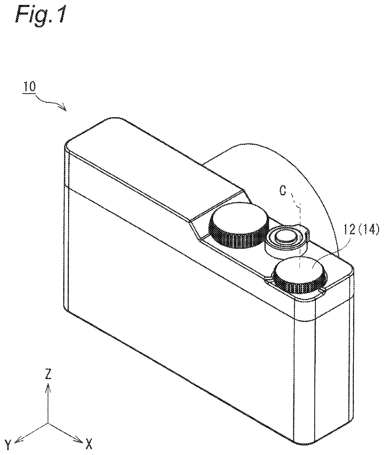
[0025]Hereinafter, an imaging apparatus according to an embodiment of the present disclosure will be described with reference to the drawings.

[0026]FIG. 1 is a perspective view schematically illustrating an imaging apparatus according to an embodiment of the pre...


PUM


Abstract

A dial device has a dial, a base member, a sphere; and a biasing member that is provided to one of the dial and the base member and biases the sphere toward the other one. An inner peripheral surface of an accommodation hole includes a portion in which a first hemispherical portion of the sphere is interposed between a first contact point and a second contact point, the first hemispherical portion of the sphere being on one side with respect to a first plane that includes the rotation direction and a biasing direction of the biasing member and passes through a center of the sphere. A recessed surface of each of a plurality of recesses includes a portion in which a second hemispherical portion of the sphere on another side with respect to the first plane is interposed between a third contact point and a fourth contact point.

Description

BACKGROUND OF THE INVENTIONField of the Invention[0001]The present disclosure relates to a dial device and an imaging apparatus including the dial device.Description of the Related Art[0002]For example, JP 11-305307 A (Patent Document 1) discloses a dial device used in an imaging apparatus. The dial device includes a dial having a plurality of click holes (recesses) on the back surface, a plurality of balls that can be engaged with the recesses of the dial, and a spring that biases a ball toward the dial in the extending direction of the rotation center line of the dial. The click holes are formed in the dial in a state of being aligned in the rotation direction of the dial in such a manner that when one ball is engaged with a click hole, the other balls do not engage with the other click holes. Thus, a click feeling is generated when the ball moves between the click holes by rotating the dial.SUMMARY OF THE INVENTION[0003]By the way, in the case of the dial device described in Pate...

Claims


Application Information

Patent Timeline
Patent Type & Authority Applications(United States)
IPC IPC(8): G05G5/06G05G1/10G03B17/02
CPCG05G5/065G05G2505/00G03B17/02G05G1/10
Inventor KUROKI, HIROYUKI
Owner PANASONIC INTELLECTUAL PROPERTY MANAGEMENT CO LTD
Why Eureka
Try Eureka