Rocket propelled drone

a drone and rocket technology, applied in the field of remote control wireless drones, can solve the problems of long time for drones to reach a desired target location, long time for drones to reach altitude, and high altitude, etc., to achieve fast propelling, low cost, and comparable or better performance.

Pending Publication Date: 2021-02-04
MARTEL RANDY
View PDF28 Cites 7 Cited by
  • Summary
  • Abstract
  • Description
  • Claims
  • Application Information

AI Technical Summary

Benefits of technology

[0009]As outlined above, drones may take a long time to reach altitude and/or may take a long time to reach a desired target location. Drones which have the power to move quickly, reach high altitudes and/or remain in the air for a long period of time are generally expensive, having large, heavy batteries, and large motors to drive their propellers or rotors. In contrast, the system of the invention provides a lighter and less expensive drone with comparable or better performance by using a rocket engine to quickly propel the drone to the desired altitude or location. Solid fuel rocket engines, for example, provide a very good power to weight ratio, and power to cost ratio.
[0010]According to one aspect of the present invention there is provided an unmanned vehicle comprising: a fuselage; a propulsion unit engaged with said fuselage, and operable to propel said unmanned vehicle to a desired altitude or location during a firing stage; multiple rotors pivotally engaged with said fuselage; and a rotor positioning system operable to pivot said multiple rotors between a stowed position and a deployed position, the stowed position minimizing drag and instability during the firing stage, and the deployed position allowing the multiple rotors to control the position and altitude of the unmanned vehicle.
[0

Problems solved by technology

As outlined above, drones may take a long time to reach altitude and/or may take a long time to reach a desired target location.
Drones which have the power to move quickly, reac

Method used


Image

  • Rocket propelled drone
  • Rocket propelled drone
  • Rocket propelled drone

Examples


Embodiment Construction

[0038]One or more currently preferred embodiments have been described by way of example. It will be apparent to persons skilled in the art that a number of variations and modifications can be made without departing from the scope of the invention as defined in the claims.

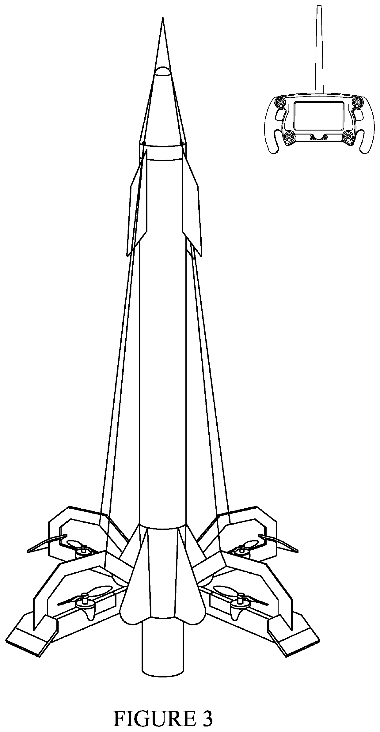
[0039]FIG. 3 presents a simplified arrangement of a rocket propelled drone in an exemplary embodiment of the invention. The primary elements of the rocket propelled drone are the fuselage, the multiple rotors which provide the drone functionality, the rotor positioning system, the cone, the tail fins, the nose fins and the wireless remote controller. The rocket propelled drone also, of course, includes a propulsion unit inside the fuselage, which is not visible in FIG. 3.

[0040]Various embodiments of the drone rocket are described herein. For example, while FIG. 3 presents an embodiment with a single set of wings / rotor assemblies, other embodiments may comprise two or more sets of wings / rotor assemblies. The first se...


PUM


Abstract

Disclosed is a remotely controlled wireless drone which employs a solid fuel rocket engine to propel it quickly to a desired or location. More specifically, an unmanned vehicle including a fuselage and a propulsion unit engaged with the fuselage, the propulsion unit being operable to bring the unmanned vehicle to a desired altitude or location, generally during a launch stage. The fuselage also includes multiple rotors pivotally engaged with the fuselage and a rotor positioning system operable to pivot the multiple rotors between stowed and deployed positions. The stowed position of the propellers minimizes drag and instability during the launch stage, and the deployed position allows the multiple rotors to control the position and altitude of the unmanned vehicle after the fuel of the rocket engine is spent. Submersible/amphibious and other embodiments are also described.

Description

CROSS REFERENCE TO RELATED APPLICATION[0001]This application claims benefit to U.S. provisional application Ser. No. 62 / 852,520, filed May 24, 2019, the contents of which are incorporated herein by reference.FIELD OF INVENTION[0002]The present invention relates to a remotely controlled wireless drone, which employs a rocket engine to propel it quickly to a desired altitude or location. More specifically, the drone comprises propellers and / or rotors which are in a stowed position while the rocket engine is firing (i.e. the propellant is burning), and are then deployed and energized once the desired or target altitude or location has been reached.BACKGROUND OF THE INVENTION[0003]Unmanned aerial vehicles (UAVs), quadcopters, octocopters and the like, commonly and collectively known as drones, are aircraft without a human pilot aboard. Compared to manned aircraft, drones were initially used in applications requiring stealth, or in applications which were considered to be too dangerous f...

Claims


Application Information

Patent Timeline
IPC IPC(8): B64C39/02B64C27/52B64D27/24B64D17/80B64D27/02B64D27/16B64C37/00
CPCB64C39/024B64C2211/00B64D27/24B64D17/80B64D27/023B64D27/16B64C37/00B64C2201/042B64C2201/046B64C2201/048B64C2201/088B64C2201/108B64C2201/141B64C2201/146B64C27/52B64U50/15B64U50/12B64U70/80B64U2201/10B64U30/20B64U50/19B64U2201/20B64U10/20B64U30/293
Inventor MARTEL, RANDY
Owner MARTEL RANDY
Why Eureka
Try Eureka