Self Venting Setting Tool That Utilizes Wellbore Fluid to Dampen Setting Motion

a setting tool and wellbore technology, which is applied in the direction of earthwork drilling, sealing/packing, and wellbore/well accessories, etc., can solve the problems of venting of the pressure within the setting tool and the undesirable effect of bringing downhole setting tools to the surfa

Inactive Publication Date: 2021-02-11
BAKER HUGHES OILFIELD OPERATIONS LLC
View PDF0 Cites 1 Cited by
  • Summary
  • Abstract
  • Description
  • Claims
  • Application Information

AI Technical Summary

Benefits of technology

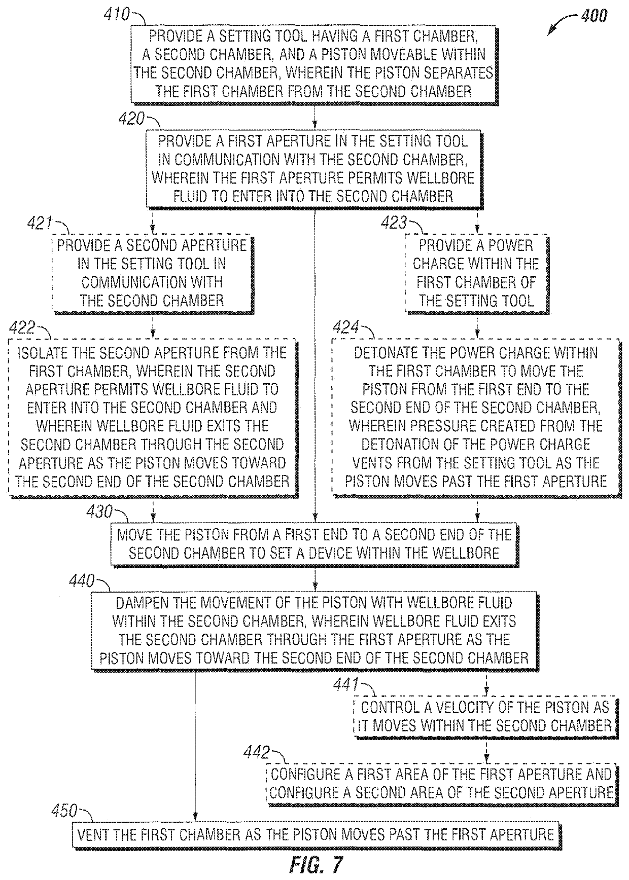
[0009]An embodiment of the present disclosure is a method comprising providing a setting tool having a first chamber, a second chamber, and a piston moveable within the second chamber, wherein the piston separates the first chamber from the second chamber. The method includes providing a first aperture in the setting tool in communication with the second chamber, wherein the first aperture permits wellbore fluid to enter into the second chamber. The method includes moving the piston from a first end to a second end of the second chamber to set a device within the wellbore. The method includes dampening the movement of the piston with wellbore fluid within the second chamber, wherein wellbore fluid exits the second chamber through the first aperture as the piston moves towards the second end of the second chamber. The method includes venting the first chamber as the piston moves past the first aperture.

Problems solved by technology

Another issue with downhole setting tools is the venting of the pressure within the setting tool after the detonation of the power charge.
It is undesirable to bring a downhole setting tool to the surface with pressure from the detonation of the power charge still contained within a portion of the setting tool.

Method used


Image

  • Self Venting Setting Tool That Utilizes Wellbore Fluid to Dampen Setting Motion
  • Self Venting Setting Tool That Utilizes Wellbore Fluid to Dampen Setting Motion
  • Self Venting Setting Tool That Utilizes Wellbore Fluid to Dampen Setting Motion

Examples


Embodiment Construction

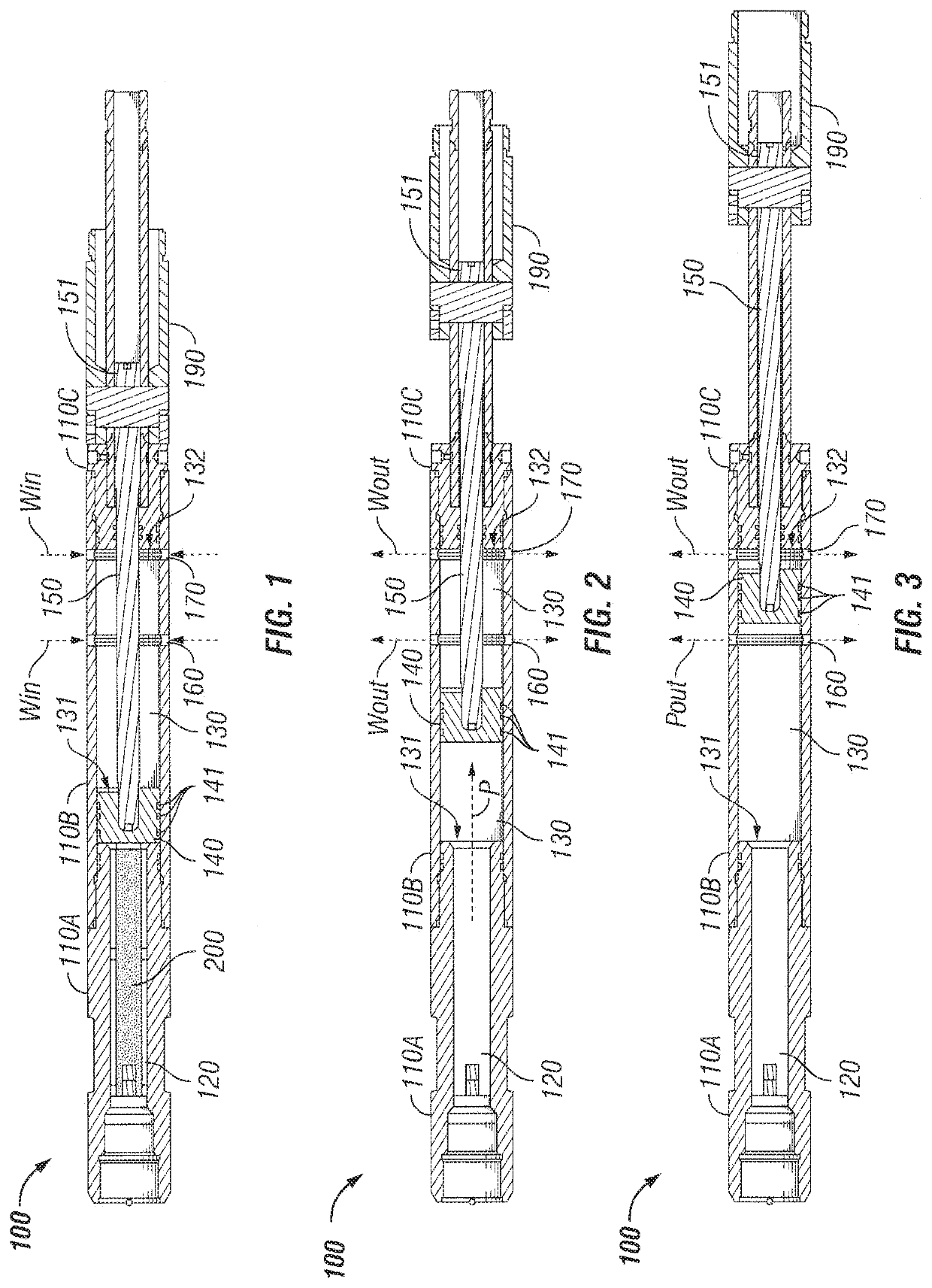
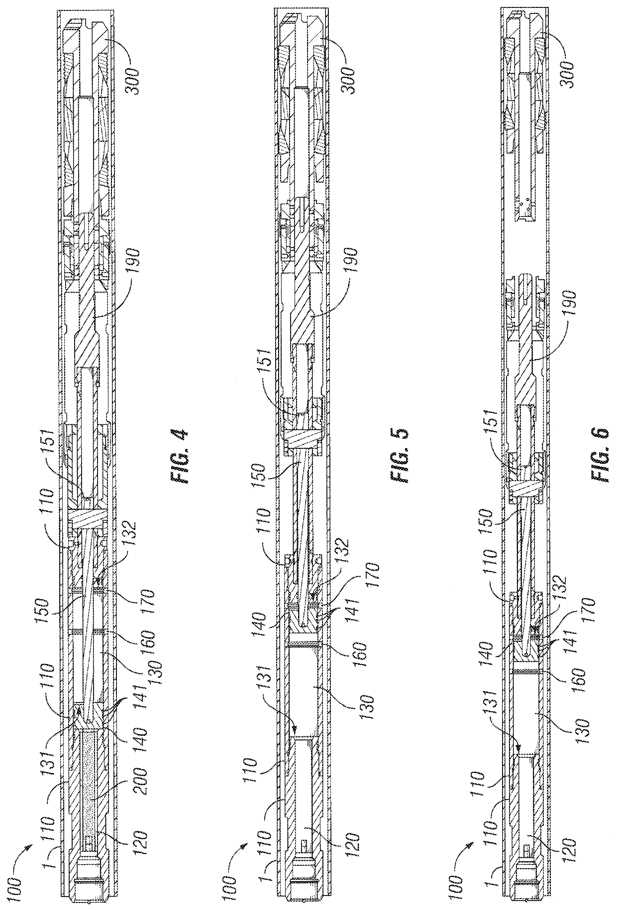
[0019]FIG. 1 shows an embodiment of a setting tool 100. The setting tool includes multiple housing sections 110A, 110B, 110C that collectively form a housing 110 (best shown in FIGS. 4-6). The number of housing sections 110A, 100B, 110C are shown for illustrative purposes only and may be varied as would be appreciated by one of ordinary skill in the art having the benefit of this disclosure. For example, the setting tool 100 may be formed from a single integral housing, but the use of multiple housing sections, such as, but not limited to, 110A, 110B, 110C may aid in the manufacturing of the setting tool 100.

[0020]The setting tool 100 includes a first chamber 120 and a second chamber 130. A piston 140 is positioned within the housing 110 of the setting tool 100. The piston 140 separates the first chamber 120 from the second chamber 130. Seals 141 located on the outside of piston 140 hydraulic isolate the first chamber 120 from the second chamber 130. The piston 140 is moveable withi...


PUM


Abstract

A setting tool for setting a device within a wellbore. The setting tool includes first and second chambers within a housing. A piston separates the chambers and is moveable within the second chamber. The piston is initially positioned adjacent a first end of the second chamber. The setting tool includes a first aperture in communication with the second chamber. Wellbore fluid may enter the second chamber through the first aperture. As the piston moves towards the second end of the second chamber, wellbore fluid within the second chamber is forced out of the second chamber through the first aperture. Pressure within the first chamber vents from the first chamber through the first aperture when the piston moves past the first aperture within the second chamber. The housing may include a second aperture adjacent to the second end of the second chamber that permits wellbore fluid to enter and exit.

Description

BACKGROUNDField of the Disclosure[0001]The embodiments described herein relate to apparatuses, systems, and methods for damping the movement of a piston within a setting tool with wellbore fluid and venting the pressure created by the detonation of a power charge within the setting tool.Description of the Related Art[0002]A downhole setting tool may use a power charge to set a device within a wellbore. The power charge is detonated to generate the force required to set the device. For example, the force from the detonated power charge may move a piston causing the setting of the device. The power charge of the downhole setting tool may be used to set various devices in a wellbore as would be appreciated by one of ordinary skill in the art. For example, a downhole setting tool with a power charge may be used to set bridge plugs, cement retainers, packers, and various other downhole devices.[0003]The force created by the detonation of the power charge can be significant. Present downh...

Claims


Application Information

Patent Timeline
Patent Type & Authority Applications(United States)
IPC IPC(8): E21B23/04E21B23/06E21B33/128
CPCE21B23/04E21B33/128E21B23/065E21B23/0414
Inventor KEHOE, STEPHEN FINBAROBERG, LEVI
Owner BAKER HUGHES OILFIELD OPERATIONS LLC
Why Eureka
Try Eureka