Wheel device applied to a mouse

a technology of a wheel and a mouse, applied in the field of mouse wheel devices, to achieve the effect of low cost and high cos

Active Publication Date: 2021-02-11
DARFON ELECTRONICS CORP
View PDF0 Cites 2 Cited by
  • Summary
  • Abstract
  • Description
  • Claims
  • Application Information

AI Technical Summary

Benefits of technology

[0010]The wheel mouse of the present invention disposes the low cost sheltering component on the roller or the wheel, to form the light sheltering areas and the light penetrating areas alternately arranged for intermittently sheltering a transmission path of the optical detecting module, and then rotation information of the wheel module and a related input command can be acquired. Arrangement of the light sheltering areas and the light penetrating areas on the sheltering component can be varied in accordance with a requirement of the outer annular region and the inner annular region. Material and a manufacturing method of the light sheltering area correspond to the position of the light sheltering area. The shape and position of the sheltering component can be adaptably adjusted according to the actual and design demands. The present invention has an advantage of high-level customized service about the optical grating structure, and the high cost roller can be matched with a variety of mice having different functions.

Problems solved by technology

With the advanced technology, design of the mouse utilizing the optical grating encoder to detect the rotary speed of the mouse roller with illumination function is an important issue in the related industry.

Method used


Image

  • Wheel device applied to a mouse
  • Wheel device applied to a mouse
  • Wheel device applied to a mouse

Examples


Embodiment Construction

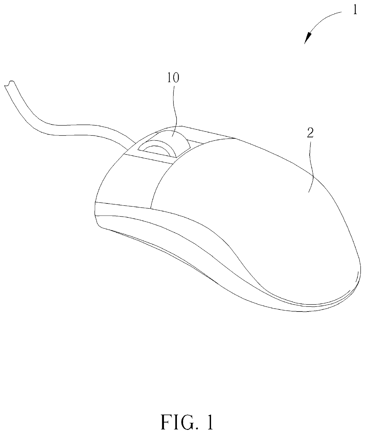
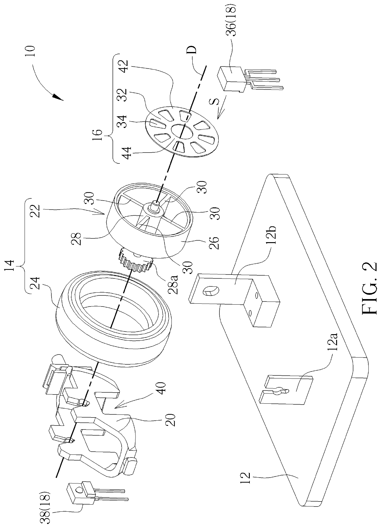
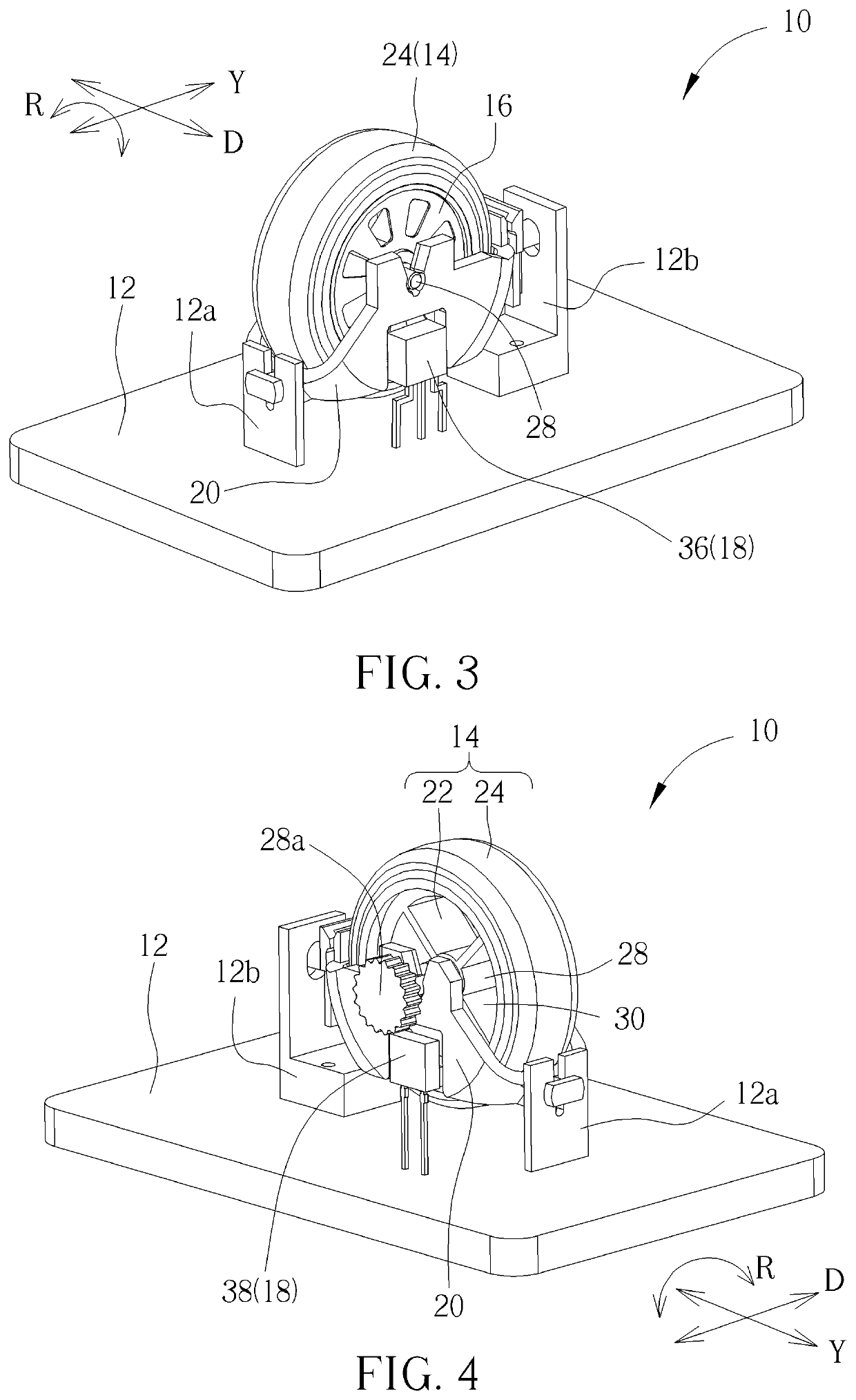
[0025]Please refer to FIG. 1 to FIG. 4. FIG. 1 is a diagram of a mouse 1 according to an embodiment of the present invention. FIG. 2 is an exploded diagram of a wheel device 10 according to a first embodiment of the present invention. FIG. 3 and FIG. 4 are diagrams of the wheel device 10 in different views according to the first embodiment of the present invention. The wheel device 10 can be disposed inside the mouse 1. Some part of the wheel device 10 may be exposed via an opening on a housing 2 for being touched by a user. The wheel device 10 can include a base 12, a wheel module 14, a sheltering component 16 and an optical detecting module 18. The base 12 can include a holder 20, and a top of the holder 20 is open to hold the wheel module 14. The holder 20 can be pivoted to a front supporter 12a and a rear supporter 12b of the base 12 in a vertical direction Y, so that the wheel module 14 and the holder 20 can be laterally rotated in a deflecting direction R. The base 12 may incl...


PUM


Abstract

A wheel device applied to a mouse includes a base, a wheel module, a sheltering component and an optical detecting module. The base has a holder. The wheel module is disposed on the base and includes a roller and a wheel. The roller includes a rolling surface, an axle and a plurality of rib structures. The axle is rotatably disposed on the holder in an axle direction. The rib structures are disposed inside the rolling surface. The wheel is disposed on the rolling surface of the roller. The sheltering component includes light sheltering areas and light penetrating areas disposed on the roller or the wheel and around the axle direction. Each light sheltering area is perpendicular to the axle. The optical detecting module has an optical emitter and an optical receiver. The optical receiver is adapted to receive an optical signal emitted by the optical emitter.

Description

BACKGROUND OF THE INVENTION1. Field of the Invention[0001]The present invention relates to a wheel device applied to a mouse, and more particularly, to a wheel device of the mouse utilizing optical detection technology to detect rotary information.2. Description of the Prior Art[0002]A roller module disposed on the top of the mouse is used to control a gesture applied for browsing the webpage. The user can control a rotary speed of the roller via fingers, and the rotary speed of the roller is relevant to a rolling speed of the webpage and information content that the user can watch within a short period.[0003]The rotary speed of the roller is detected by an encoder, and a mechanical encoder is widespread applied to the mouse. Comparing to an optical grating encoder, the mechanical encoder of the conventional mouse has properties of simply structure, easy programmable control and specific hand feeling. The mechanical encoder includes a turntable. When the mouse roller rotates the tur...

Claims


Application Information

Patent Timeline
Patent Type & Authority Applications(United States)
IPC IPC(8): G06F3/0362G06F3/0354
CPCG06F3/0362G06F3/03543G06F3/0312G06F3/0317
Inventor SU, CHEN-YUNHSU, DA-SHANHSIAO, SHAO-LUNCHAO, LING-HSI
Owner DARFON ELECTRONICS CORP
Why Eureka
Try Eureka