Face mask and method for manufacturing thereof

a face mask and mask technology, applied in the field of face masks, can solve the problems of pain and discomfort, transfer of pathogens through gaps,

Active Publication Date: 2021-02-18
TSUEI ALEXANDER CHIERUEN
View PDF0 Cites 3 Cited by
  • Summary
  • Abstract
  • Description
  • Claims
  • Application Information

AI Technical Summary

Benefits of technology

[0005]The present application discloses a face mask and method of manufacturin

Problems solved by technology

However, such face mask often causes pain and discomfort due to the metal material.
In addition, the gaps between the face mas

Method used


Image

  • Face mask and method for manufacturing thereof
  • Face mask and method for manufacturing thereof
  • Face mask and method for manufacturing thereof

Examples


first embodiment

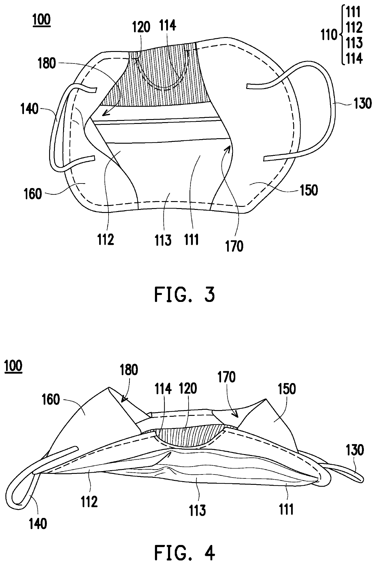
[0053]FIGS. 3-4 are views showing a first chamber 170 and a second chamber 180 of the face mask 100 according to the

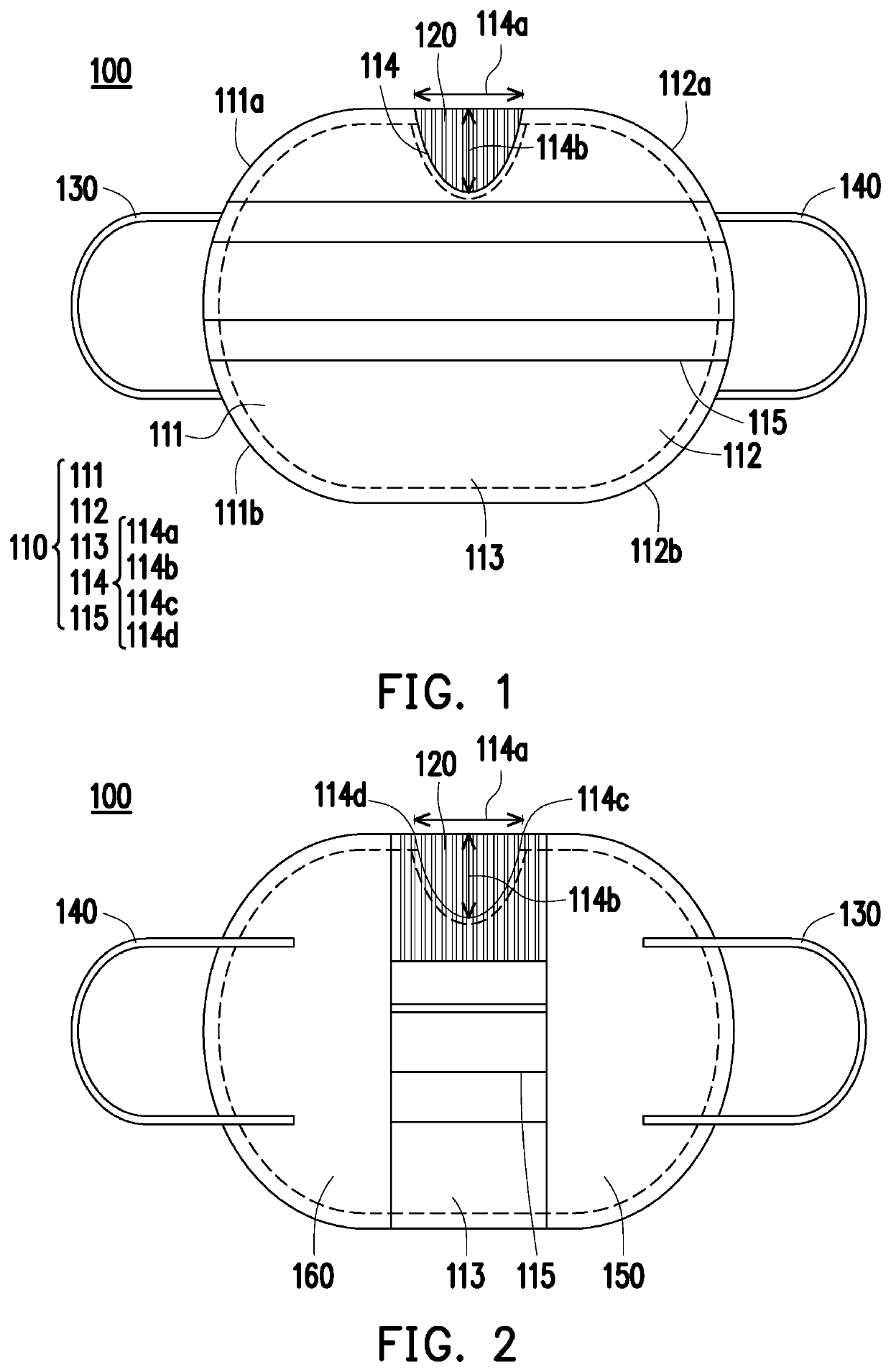
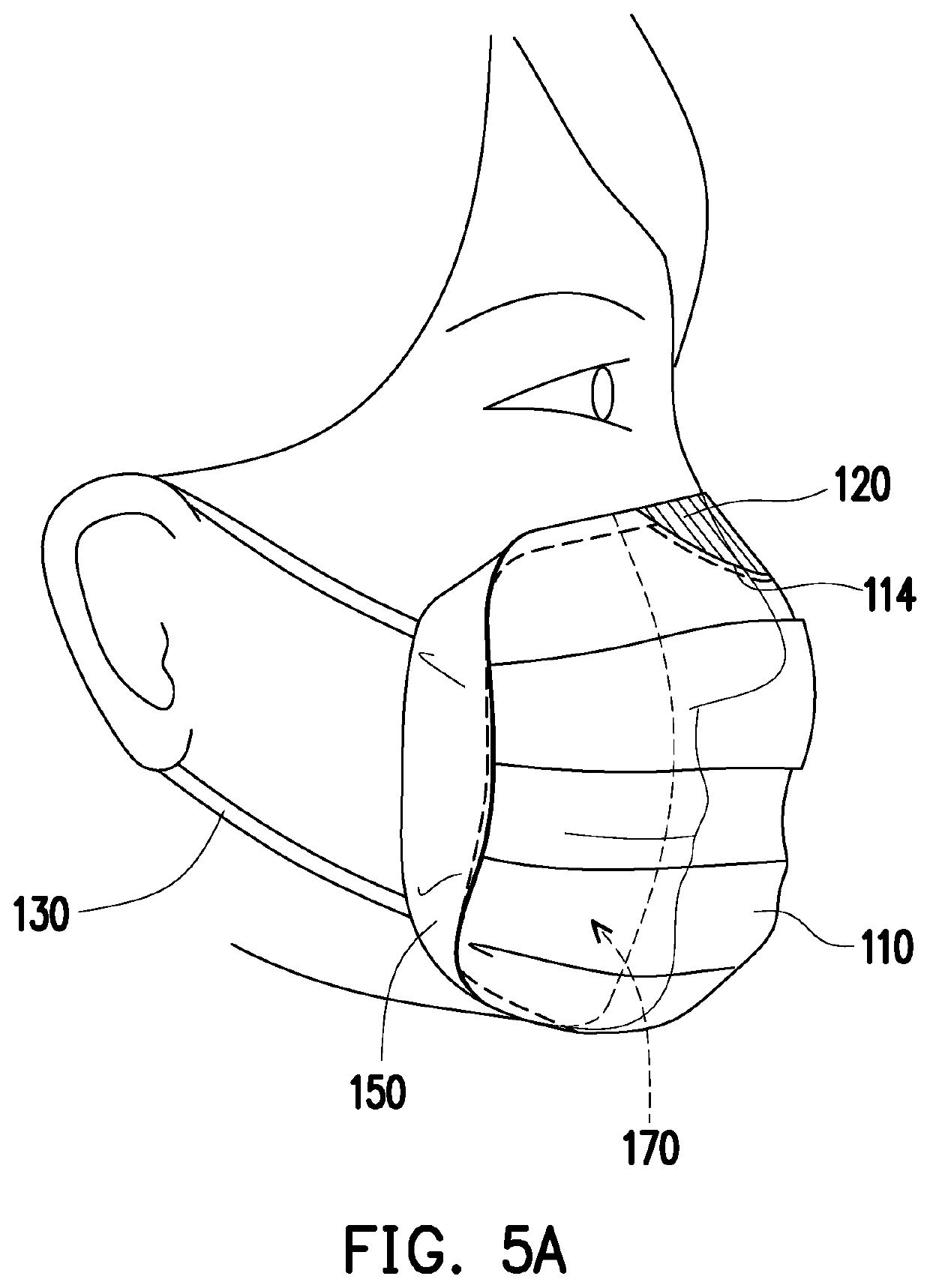
[0054]Referring to FIGS. 2-4, the first lateral flap 150 is coupled to the first lateral portion 111 to form the first chamber 170. The second lateral flap 160 is coupled to the second lateral portion 112 to form the second chamber 180. Therefore, in a worn state, the first loop 130 and the second loop 140 may cause the upper and lower ends of the face mask 100 to be led inward to approximate the face, allowing all edges of the face mask 100 to create a better seal.

[0055]As shown in FIG. 2, the widest portion 114a of the opening 114 comprises a first end 114c and a second end 114d. A distance between the first lateral flap 150 and the first end 114c is greater than 0 inch. A distance between the second lateral flap 160 and the second end 114d is greater than 0 inch.

[0056]Corners of the first lateral flap 150 and the second lateral flap 160 may be curved as the first la...

second embodiment

[0086]FIG. 14 is a view showing the face mask 200 during a folded mode.

[0087]As shown in FIG. 14 and referring to FIG. 13, when folding back the face mask 200 from the unfolded mode, the oblique pleat 215c and the oblique pleat 215d will be hidden.

[0088]FIGS. 15A-15B are views showing a method of manufacturing the face mask of the second embodiment.

[0089]Referring to FIGS. 7-8 and 15A-15B, a system 290 comprises a die cut station 291, a pleating station 292, a pleating station 293, a bonding station 294, a bonding station 295 and a die-cut station 296.

[0090]First, preparing the material of the sheet 210 and passing it to the die-cut station 291 to form the opening 214. Second, preparing the material of the elastic film 220 and passing it with the material of the sheet 210 for the next step.

[0091]Next, pleating the material of the sheet 210 to form the first vertical pleat 218a / 218b and the second vertical pleat 219a / 219b via the pleating station 292. After that, pleating the materi...


PUM


Abstract

The present application discloses a mask including a sheet, a first loop, a second loop and an elastic film. The sheet comprises a central portion, a first lateral portion, a second lateral portion and an opening. The first loop is coupled to the sheet. The second loop is coupled to the sheet. The elastic film is coupled to the sheet and covers the opening. A method of manufacturing the aforementioned face mask is also disclosed.

Description

TECHNICAL FIELD OF THE INVENTION[0001]The present application generally relates to face masks, and more particularly, to a face mask and a method for manufacturing the face mask.BACKGROUND OF THE INVENTION[0002]Face masks are useful in a number of fields. For example, in the health care field, a face mask may be useful for protecting both the patient and the health care provider from airborne pathogens or for preventing the transfer of pathogens that reside in the bodily fluids or other liquids. Wearing face masks may also be useful in many industrial settings.[0003]Current face mask comprises a metal nose piece at the nose portion for more stably wearing the face mask onto the wearer according to the shape of the nose. However, such face mask often causes pain and discomfort due to the metal material. In addition, the gaps between the face mask and the nose may be appeared along with the facial muscle movement, resulting in the transfer of pathogens through the gaps.[0004]Therefore...

Claims


Application Information

Patent Timeline
IPC IPC(8): A41G7/00
CPCA41G7/00A41D13/1115A41D13/113A41D13/1161A41D13/1107A41D13/11A41D27/02A41D31/18A41H42/00A41H43/00A41D2300/33A41D2300/22
Inventor TSUEI, ALEXANDER CHIERUEN
Owner TSUEI ALEXANDER CHIERUEN
Why Eureka
Try Eureka