
Dynamic sweep angle measurement for fault monitoring of windshield wiper systems

a technology of windshield wipers and sweep angles, which is applied in vehicle maintenance, vehicle cleaning, transportation and packaging, etc., can solve the problem that wws is not typically expected to have any movement or flutter

Active Publication Date: 2021-02-18
ROSEMOUNT AEROSPACE
View PDF2 Cites 0 Cited by
  • Summary
  • Abstract
  • Description
  • Claims
  • Application Information

AI Technical Summary

Benefits of technology

The invention provides a system for monitoring the angle of a wiper blade assembly in real-time during operation. This monitoring can detect any issues with the motor, wiper blade assembly, or the gear train between the motor and wiper blade assembly. This allows for quick identification of any failures or ageing issues, which can prevent damage or malfunction.

Problems solved by technology

The WWS is not typically expected to have any movement or flutter when it is non-operational under all loading conditions.

Method used


Image

  • Dynamic sweep angle measurement for fault monitoring of windshield wiper systems
  • Dynamic sweep angle measurement for fault monitoring of windshield wiper systems
  • Dynamic sweep angle measurement for fault monitoring of windshield wiper systems

Examples


Embodiment Construction

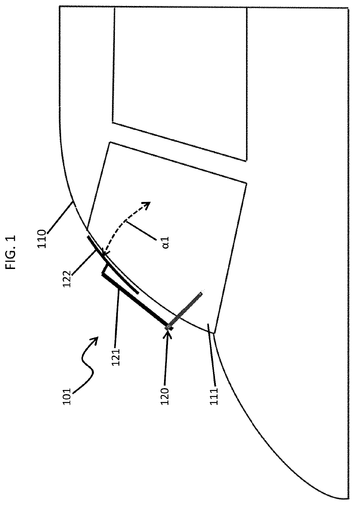
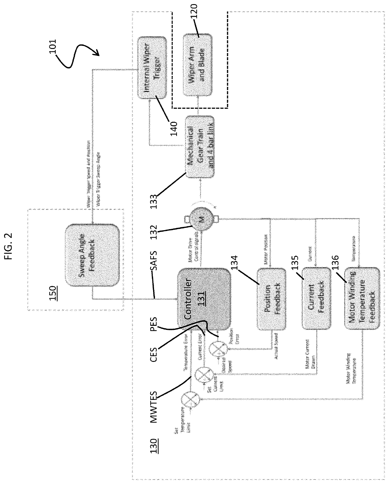
[0034]A conventional WWS can include an intelligent device with a controller or processor that provides a motor commutation sequence and monitors system faults, an internal wiper trigger that detects an end of sweep position of an external wiper blade, a park sensor feedback system with an end of sweep (EoS) sensor that detects the end of sweep position of the WWS by monitoring the internal wiper trigger, Hall sensor feedback to measure a speed of a motor of the WWS, motor current feedback to monitor motor winding currents, motor winding temperature feedback to monitor temperatures of the motor windings, a mechanical gear train and four bar link mechanism and a wiper arm and blade. The mechanical gear train and the four bar link mechanism converts rotary motion of the motor to oscillatory motion and the wiper arm and blade is driven by the oscillatory motion to wipe the windshield.

[0035]Thus, in the conventional WWS, it is seen that Hall sensors are used to detect a speed of the mot...


PUM


Abstract

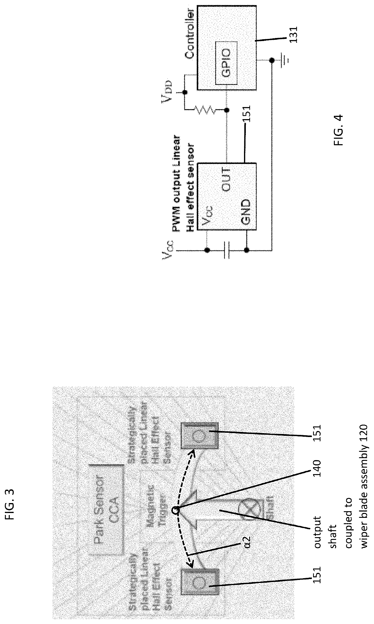
A windshield wiper system (WWS) is provided and includes a wiper blade assembly drivable along a first sweep angle, an internal wiper trigger disposed to move with the wiper blade assembly, a measurement system configured to monitor a position of the internal wiper trigger from which a corresponding position of the wiper blade assembly relative to the first sweep angle is measurable and to output a sweep angle feedback signal corresponding to monitoring results and a controller. The controller is receptive of the sweep angle feedback signal.

Description

CROSS REFERENCE TO RELATED APPLICATION[0001]This application claims the benefit of Indian Patent Application No. 201911032887, filed Aug. 14, 2019, which is incorporated herein by reference in its entirety.BACKGROUND[0002]The following description relates to windshield wiper systems (WWSs) and, more specifically, to dynamic sweep angle measurement for fault monitoring of a WWS.[0003]A WWS is typically employed on a vehicle, such as an aircraft, to clear moisture or foreign object debris from a windshield and to allow for improved visibility. For example, a WWS on an aircraft can be used to improve visibility for pilots or co-pilots during take-off or landing operations.[0004]To ensure that a WWS provides for required coverage on a windshield, the WWS will generally be designed to move through a specific wipe or sweep angle. This sweep angle can be controlled with or without a four bar mechanism designed to configured the WWS to sweep through the specific angle and return to a park p...

Claims


Application Information

Patent Timeline
Patent Type & Authority Applications(United States)
IPC IPC(8): B60S1/34B60S1/08B60S1/26
CPCB60S1/3409B60S1/26B60S1/08
Inventor MANJUNATH, ARUNAMOTHE, VENKATA ANIL KUMARVADGAONKAR, PRASHANT
Owner ROSEMOUNT AEROSPACE
Learn More