Magnetic resonance imaging using demodulated k-space segments

a magnetic resonance imaging and demodulation technology, applied in the field of magnetic resonance imaging systems, can solve the problems of neural stimulation, poor snr, and exceeding the fda db/dt limi

Inactive Publication Date: 2006-07-25
MACOVSKI ALBERT
View PDF3 Cites 4 Cited by
  • Summary
  • Abstract
  • Description
  • Claims
  • Application Information

AI Technical Summary

Benefits of technology

[0009]A further object of this invention is to provide MRI images of rapidly moving objects, such as the beating heart, with negligible errors.

Problems solved by technology

Firstly, the short imaging period would result in a poor SNR as shown in the journal paper by A. Macovski, “Noise in MRI”, Magn Reson Med 36:494–497, 1996.
In addition, attempts at very rapid gradient speeds to cover all of k-space often result in exceeding the FDA dB / dt limits, causing neural stimulation.
The problem with these approaches is that motion or other changes occur between the acquisitions of these sequences.
However, as a result of the changes between sequences, significant artifacts result because of the inconsistent k-space data.

Method used


Image

  • Magnetic resonance imaging using demodulated k-space segments
  • Magnetic resonance imaging using demodulated k-space segments
  • Magnetic resonance imaging using demodulated k-space segments

Examples


Embodiment Construction

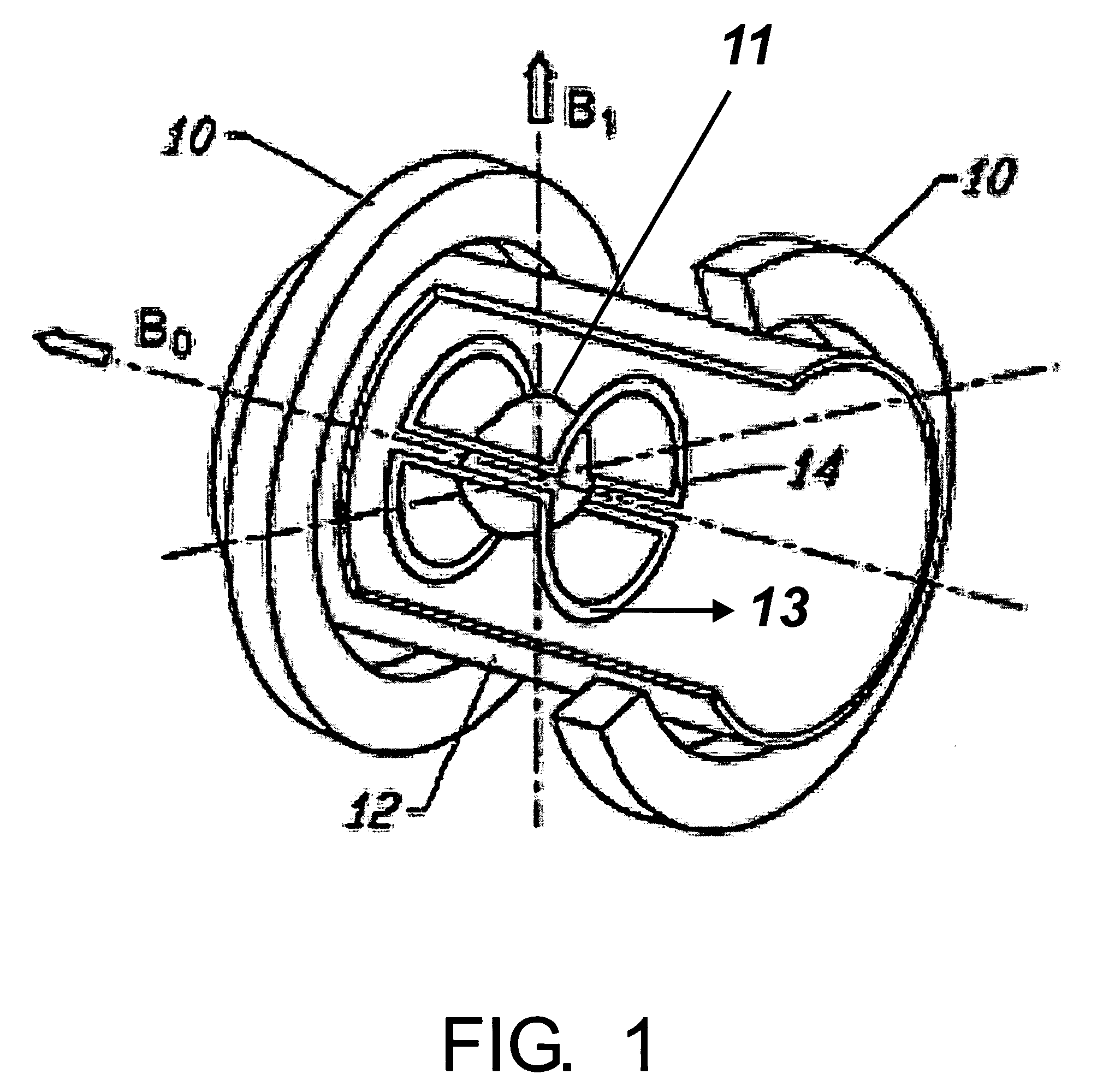
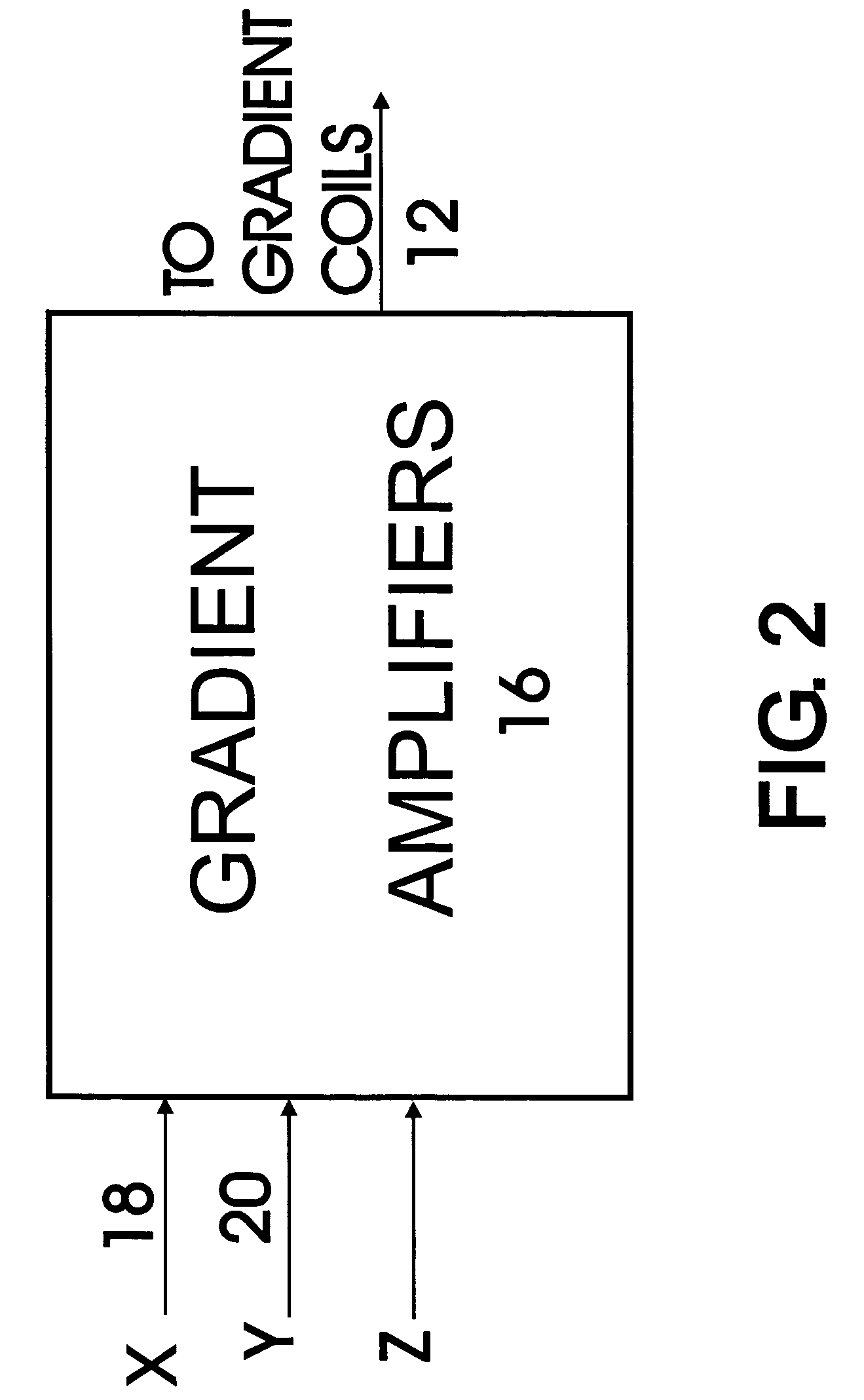
[0023]An understanding of the broad aspects of the invention can best be had by reference to FIG. 1. Here we basically see the structures of an MRI system as described in the book by P. Mansfield and P. G. Morris in “NMR Imaging in Biomedicine”, Academic Press, Inc., Orlando Fla., 1982. Here it is used to image object 11 that is normally a portion of the human body. The magnetic moments in the body are polarized using solenoidal magnet 10. A set of gradient coils on cylinder 12 provide fields pointed in the same direction as the B0 field created by magnet 10. These are made spatially varying to provide imaging information while the magnetic moments are precessing. Using these coils, variations can be made in the x, y, or z axes representing the three gradient fields, all pointing in the B0 direction. These provide gradient fields as given by:

Gx=d / dx B0

Gy=d / dy B0

Gz=d / dz B0.

These gradient fields are used, while the moments are precessing, to create linear space-varying fields to provi...


PUM


Abstract

In an MRI imaging system each portion of k-space is sequentially scanned, transformed and separately demodulated. Instead of adding the k-space regions, as is the practice in the prior art, the demodulated portions are added, each representing spectral portions of the image. Each k-space portion is scanned with closely spaced lines which substantially satisfy the sampling requirement to avoid aliasing. In this way, distortion resulting from phase changes between k-space scans is avoided.

Description

CROSS REFERENCE to RELATED APPLICATIONS[0001]Not ApplicableSTATEMENTS REGARDING FEDERALLY SPOSERED RESEARCH or DEVELOPMENT[0002]Not ApplicableBACKGROUND OF THE INVENTION[0003]1. Field of the Invention[0004]This invention relates to magnetic resonance imaging systems. In a primary application this invention involves an MRI system that acquires a sequence of portions of the k-space of an image. Each individual portion of k-space is separately transformed and demodulated. The demodulated portions, each representing different spectral portions of the image, are summed.[0005]2. Description of Related Art[0006]The basic concepts in magnetic resonance are described in a series of papers in the June 1980 series of the IEEE Transactions on Nuclear Science, Vol. NS-27, pp 1220–1255. A detailed description of MRI is given in the paper by W. S. Hinshaw and A. H. Lent, “An introduction to NMR imaging: From the Bloch equation to the imaging equation”, Proceedings of the IEEE, 71(3):338–350, March...

Claims


Application Information

Patent Timeline
Patent Type & Authority Patents(United States)
IPC IPC(8): G01V3/00
CPCG01R33/565G01R33/5608G01R33/56536G01R33/56518G01R33/56509
Inventor MACOVSKI, ALBERT
Owner MACOVSKI ALBERT
Why Eureka
Try Eureka