Self-power-generating water outflow device with a light

a self-power-generating, water-outflow technology, applied in semiconductor devices, lighting and heating equipment, with built-in power, etc., can solve the problems of long service life of led lamps, high cost, and waste of resources, so as to ensure the stability of contact, reduce replacement costs, and facilitate us

Active Publication Date: 2021-02-18
XIAMEN LOTA INT CO LTD
View PDF0 Cites 6 Cited by
  • Summary
  • Abstract
  • Description
  • Claims
  • Application Information

AI Technical Summary

Benefits of technology

[0014]Compared with the background art, the technical solution has the following advantages. First, since the connector and the water outflow terminal can be separated, the self-power-generating component can be separated from the LED light source. When the LED light source is not damaged but the self-power-generating component is damaged, the connector can be replaced in time while the original water outflow terminal can be retained. This can greatly reduce replacement cost. Second, the first positive electrode and the first negative electrode are both sheets, and the one or more second positive electrodes and the one or more second negative electrodes are both column-shaped bodies. When the connector and the water outflow terminal are assembled, the column-shaped bodies of the one or more second positive electrodes and the one or more second negative electrodes easily contact the sheets of the first positive electrode and the first negative electrode. Third, the first positive electrode is an annular sheet, and the first negative electrode is a circular sheet. When the connector is rotatably screwed to the water outflow terminal, the annular sheet and the circular sheet can be better adapted to the rotation of the connector. Fourth, there are two second positive electrodes symmetrically arranged, which further ensures the stability of the contact between the two second positive electrodes and the first positive electrode. Fifth, the water outflow device further comprises a limiting mechanism configured to control rotation of the impeller. When the connector needs to perform a water outflow test independently, the rotation of the impeller can be restricted by the limiting mechanism to prevent the power generator from burning out due to the energy the power generator generates when the impeller rotates. Sixth, the limiting mechanism has a movable limit column structure, and the structure of the limiting mechanism is simple and easy to use.

Problems solved by technology

The LED lamp has a long service life and is expensive, while the micro power generator has a short service life and is inexpensive.
When the micro power generator is damaged, the entire showerhead must be replaced even if the LED lamp is not damaged, resulting in great waste of resources.

Method used


Image

  • Self-power-generating water outflow device with a light
  • Self-power-generating water outflow device with a light
  • Self-power-generating water outflow device with a light

Examples


first embodiment

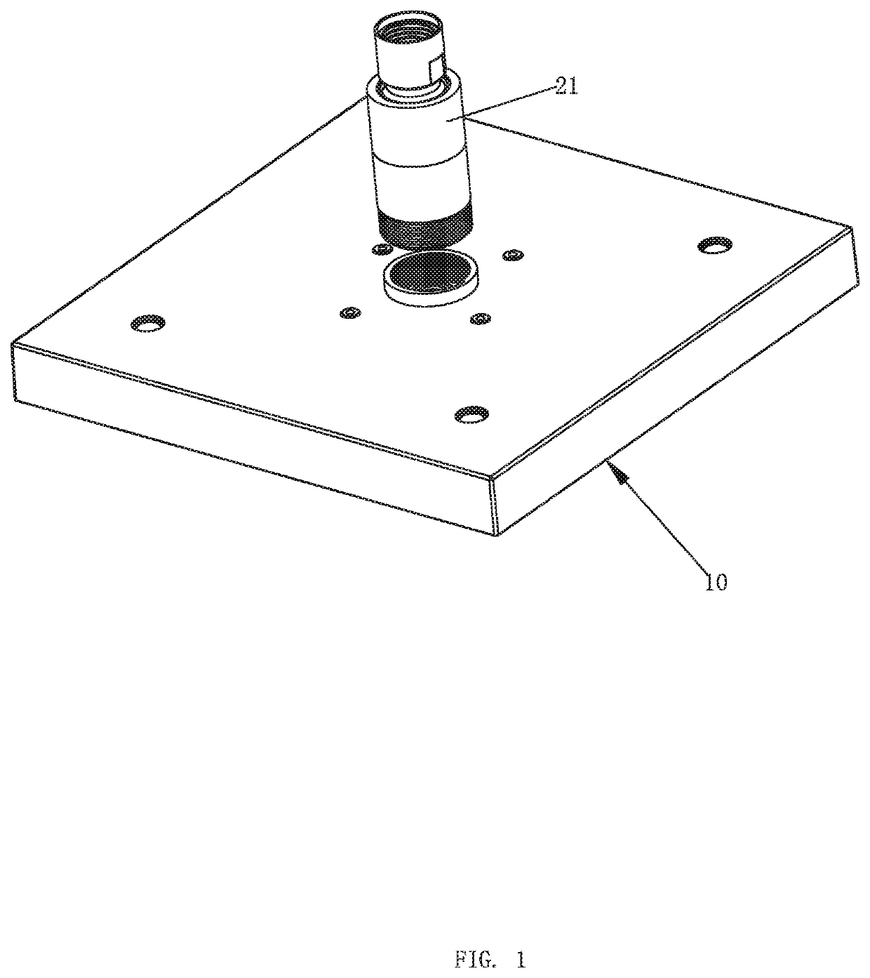
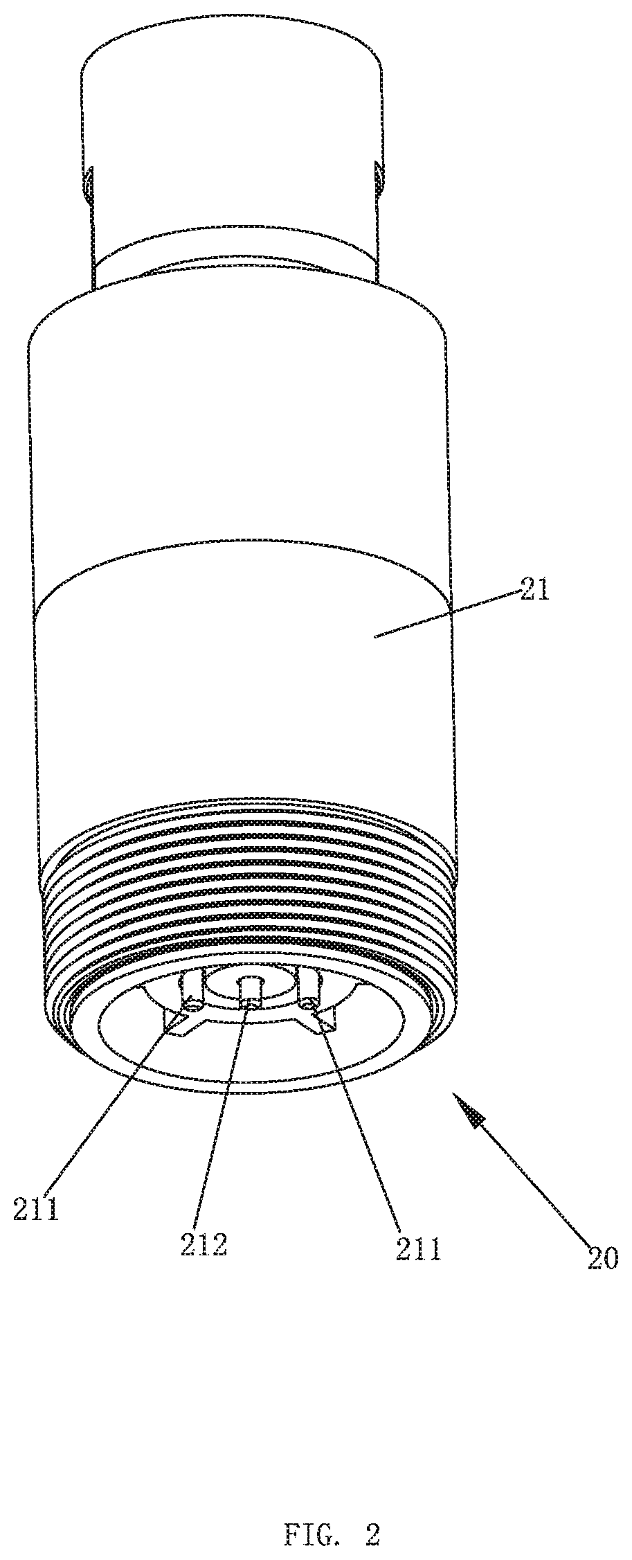
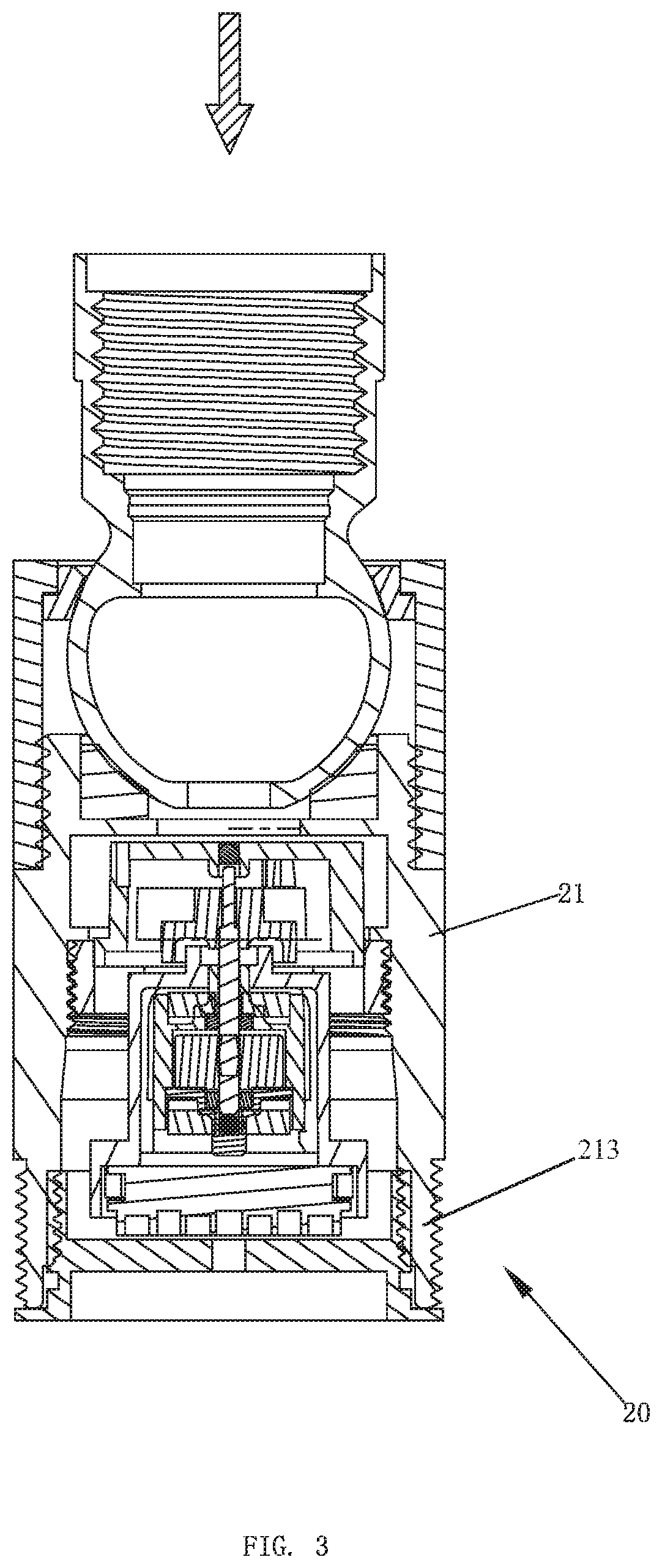
[0023]Please refer to FIG. 1 to FIG. 6, a self-power-generating water outflow device with a light comprises a water outflow terminal 10 and a connector 20.

[0024]An inner side of the water outflow terminal 10 comprises a light emitting diode (LED) light source 11 and a driving circuit for driving the LED light source (not shown). The water outflow terminal 10 further comprises a first positive electrode 31 and a first negative electrode 32 electrically connected to the driving circuit. As shown in FIG. 5, the LED light source 11 is disposed on an outer circumference of a water outflow 101 of the water outflow terminal 10.

[0025]In this embodiment, a top of the water outflow terminal 10 comprises an assembly cavity 12.

[0026]In this embodiment, a bottom wall of the assembly cavity 12 comprises a first accommodating groove 121 and a second accommodating groove 122. The first positive electrode 31 and the first negative electrode 32 are both sheets and are respectively fixedly disposed in...

second embodiment

[0035]In a second embodiment, as shown in FIG. 7, the water outflow terminal 10 further comprises a limiting mechanism 30 configured to control rotation of the impeller 23. The limiting mechanism 30 is disposed on the connection housing 21.

[0036]In the second embodiment, the limiting mechanism 30 is a limiting column laterally and movably disposed on the connection housing 21, and the limiting column moves laterally between a position abutting the impeller 23 and a position away from the impeller 23. Specifically, a threaded hole may be disposed on a side wall of the connection housing 21, and an external thread is disposed on an outer circumference of the limiting column. A threaded engagement of the threaded hole and the external thread enables the limiting column to be laterally and movably disposed on the connection housing 21. When rotation of the impeller 23 needs to be limited, it is only necessary to rotate the limiting column to cause an end of the limiting column to be loc...


PUM

PropertyMeasurementUnit
timeaaaaaaaaaa
rotationaaaaaaaaaa
stabilityaaaaaaaaaa

Abstract

Disclosed is a self-power-generating water outflow device with a light. An LED light source and a driving circuit for driving the LED light source are disposed in a water outflow terminal, and a first positive electrode and a first negative electrode are electrically connected to the driving circuit. A connector is detachably connected to the water outflow terminal. The connector comprises a connection housing and a self-power-generating component. The self-power-generating component is disposed in the connection housing, and the connection housing comprises one or more second positive electrodes and one or more second negative electrodes electrically connected to the self-power-generating component. When the connector is connected to the water outflow terminal, the first positive electrode is in contact with the one or more second positive electrodes and the first negative electrode is in contact with the one or more second negative electrodes.

Description

RELATED APPLICATIONS[0001]This application is a continuation of and claims priority to Chinese patent application number 201921332006.3, filed on Aug. 16, 2019, which is incorporated herein by reference.FIELD OF THE DISCLOSURE[0002]The present disclosure relates to a self-power-generating water outflow device with a light.BACKGROUND OF THE DISCLOSURE[0003]Existing self-power-generating water outflow devices with a light, such as disclosed in the Chinese patent application number CN105750103B and titled “A self-power-generating showerhead with a light and the working method thereof”, can supply power for a light emitting diode (LED) lamp through a micro power generator. However, as can be seen from the specification and the drawings, the micro power generator and the LED lamp are fixedly mounted in a housing. The LED lamp has a long service life and is expensive, while the micro power generator has a short service life and is inexpensive. When the micro power generator is damaged, th...

Claims


Application Information

Patent Timeline
Patent Type & Authority Applications(United States)
IPC IPC(8): F21S9/04F21V33/00
CPCF21S9/046F21Y2115/10F21V33/004B05B1/185B05B15/654B05B1/18
Inventor WANG, XUEDONGLI, ZHIYONGZHU, CHUANBAO
Owner XIAMEN LOTA INT CO LTD
Why Eureka
Try Eureka